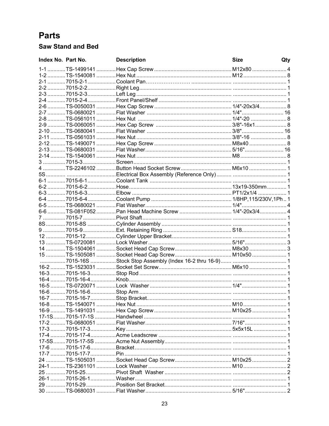
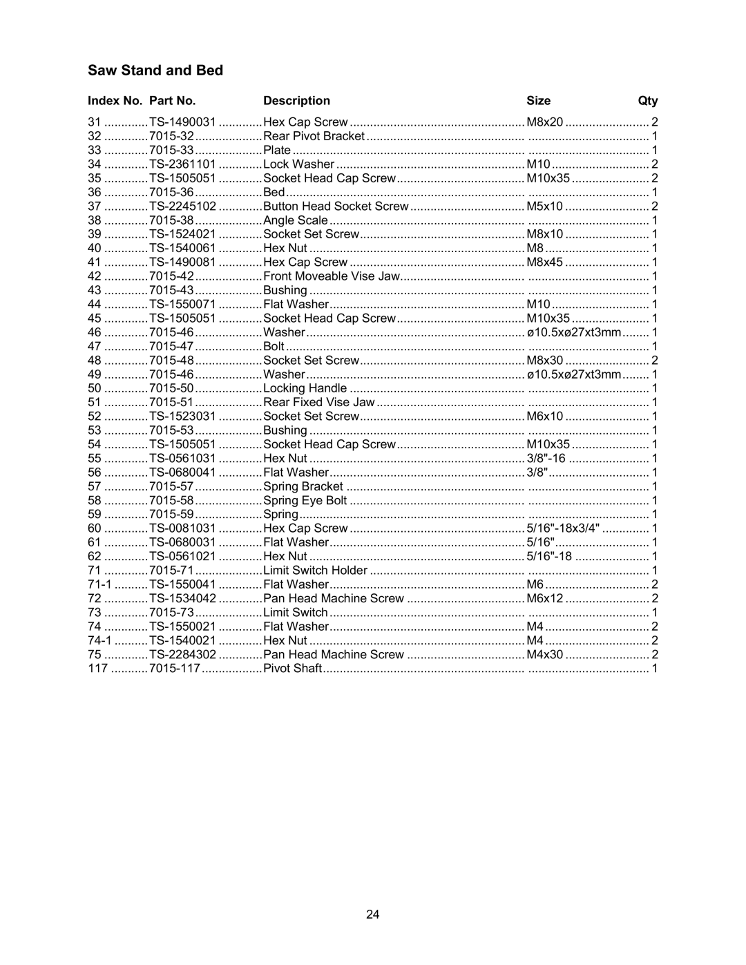
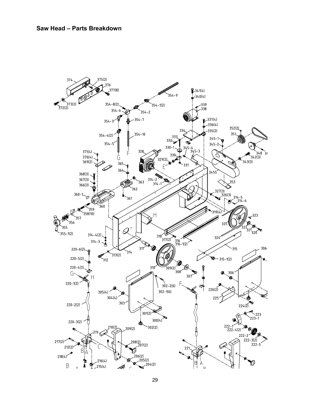
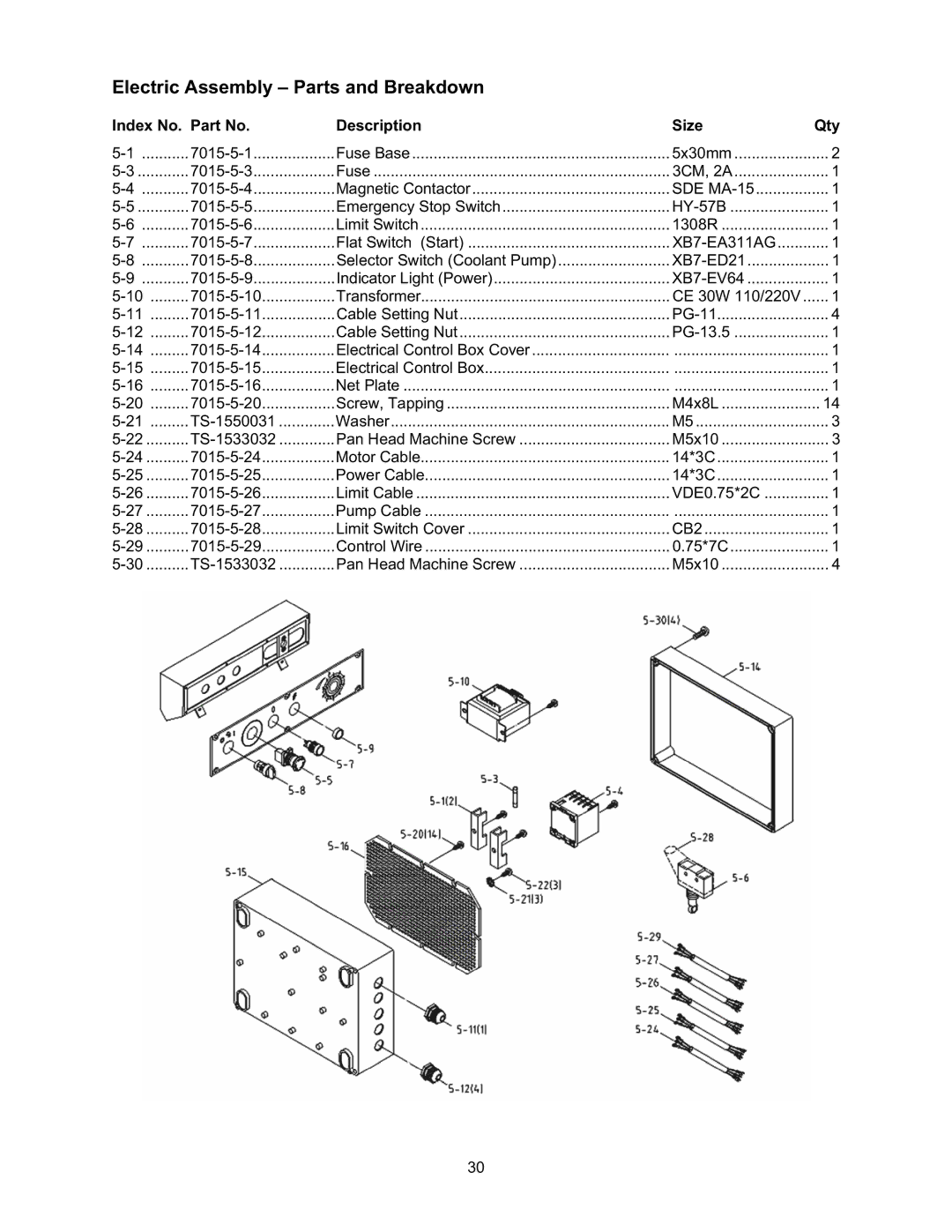
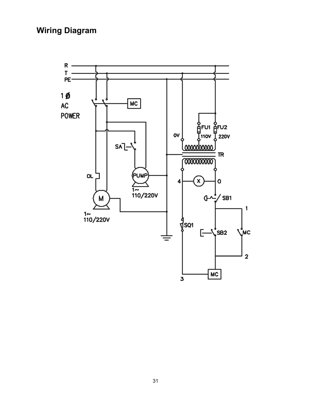
Wilton 7015 manual Index No Description Size Qty

Page 28

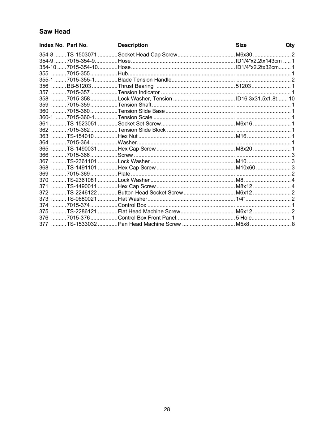
Saw Head

Index No.

Part No.

Description

Size

Qty

354-8

TS-1503071

Socket Head Cap Screw

M6x30

2

354-9

7015-354-9

Hose

ID1/4"x2.2tx143cm

1

354-10

7015-354-10

Hose

ID1/4"x2.2tx32cm

1

355

7015-355

Hub

....................................

1

355-1

7015-355-1

Blade Tension Handle

....................................

2

356

BB-51203

Thrust Bearing

51203

1

357

7015-357

Tension Indicator

....................................

1

358

7015-358

Lock Washer, Tension

ID16.3x31.5x1.8t

10

359

7015-359

Tension Shaft

....................................

1

360

7015-360

Tension Slide Base

....................................

1

360-1

7015-360-1

Tension Scale

....................................

1

361

TS-1523051

Socket Set Screw

M6x16

1

362

7015-362

Tension Slide Block

....................................

1

363

TS-154010

Hex Nut

M16

1

364

7015-364

Washer

....................................

1

365

TS-1490031

Hex Cap Screw

M8x20

1

366

7015-366

Screw

....................................

3

367

TS-2361101

Lock Washer

M10

3

368

TS-1491101

Hex Cap Screw

M10x60

3

369

7015-369

Plate

....................................

2

370

TS-2361081

Lock Washer

M8

4

371

TS-1490011

Hex Cap Screw

M8x12

4

372

TS-2246122

Button Head Socket Screw

M6x12

2

373

TS-0680021

Flat Washer

1/4"

2

374

7015-374

Control Box

....................................

1

375

TS-2286121

Flat Head Machine Screw

M6x12

2

376

7015-376

Control Box Front Panel

5 Hole

1

377

TS-1533032

Pan Head Machine Screw

M5x8

8

28

Image 28
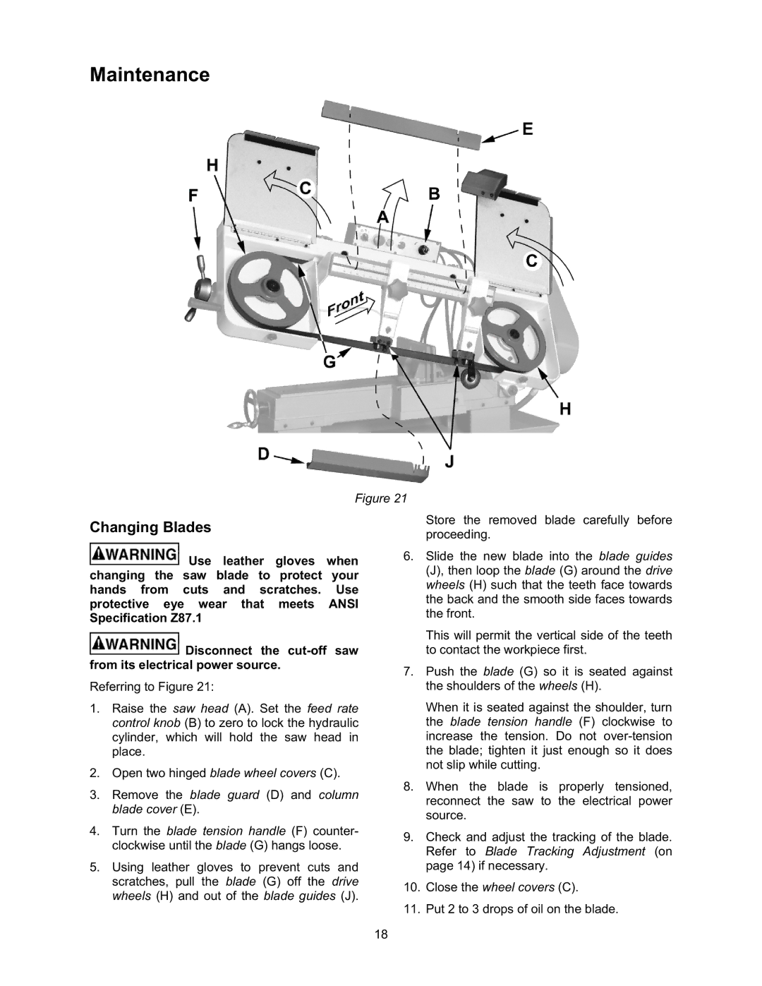
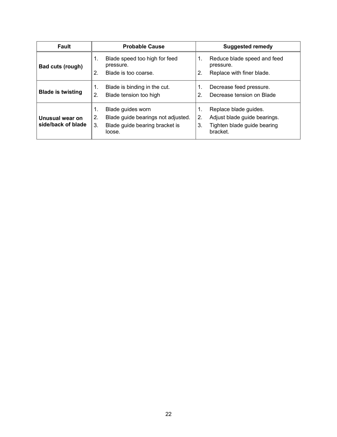
Contents X 13-in Horizontal Cut-Off Bandsaw Part No. M-7015Warranty and Service WarrantyTable of Contents Page Page Specifications IntroductionMachine Base Machine FeaturesSaw Head Unpacking and Assembly Machine SetupElectrical Connection Work StopControls and Indicators Blade SpeedsBlade Break-in Procedures Blade SelectionOperations Hydraulic Feed ControlWork Setup Setting The Vise For Angle CutsSetting the Vise for Square Cuts Evaluating Cutting EfficiencyStarting the Saw Saw will automatically shut off at the end of the cutSetting the Work Stop Coolant Flow and Nozzle PositionBlade Tracking Adjustment AdjustmentsKeep fingers clear of the blade and wheel to avoid injury Blade Guide Adjustment Left Blade GuideBlade Guide Bearing Adjustment Drive Belt Tension AdjustmentVerifying Adjustment Accuracy Switch AdjustmentDisconnect the cut-off saw from its electrical power source Counterbalance Spring TensionMaintenance Changing BladesChanging the Drive Belt Replacing the Drive MotorLubrication CleaningCoolant Fault Excessive blade breakage TroubleshootingBad cuts crooked Probable Cause Suggested remedy Fault Probable Cause Suggested remedy Bad cuts roughBlade is twisting Unusual wear onSaw Stand and Bed PartsIndex No. Part No Description Size Qty TS-1490031 Saw Stand and Bed Parts Breakdown 7015-200 7015-314-1 Index No Description Size Qty Saw Head Parts Breakdown Electric Assembly Parts and Breakdown SDE MA-15Wiring Diagram Ordering Replacement Parts WMH Tool Group