 Repair
P 7/ 15
[3]DISASSEMBLY/ASSEMBLY
[3]-6. Spring section (cont.)
ASSEMBLING
(1) Take the reverse steps of the disassembling procedure for Spring section.
(2) Fix Spur gear 55 complete with Flat washer 4 and Bind PT3x16 Tapping screw.
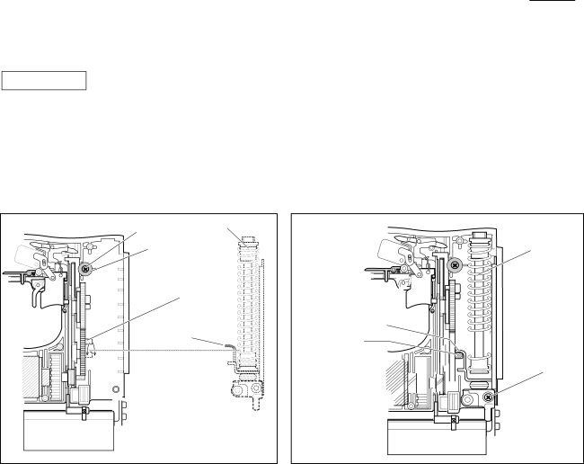
Install Spring section in Housing L while adjusting Roller position of Spur gear 55 complete to under the hook portion of hammer (Fig. 24).
(3)Fix Spring section with Bind PT3x16 Tapping screw and mount driver guide, driver, and driver guide cover to Housing R. (Fig. 25)
Fig. 24
Fig. 25
Bind PT3x16 Tapping screw | Spring section |
Flat washer 4 | |
Roller portion of | |
Spur gear 55 | |
Hook portion of | |
Hammer |
|
Hook portion ![]() of Hammer
of Hammer
Roller![]()
![]()
![]() (The position
(The position ![]()
![]()
![]()
![]()
![]()
![]()
![]() is lower than
is lower than ![]()
![]()
![]()
![]()
![]()
![]()
![]()
![]()
![]()
![]() that of the hook
that of the hook ![]()
![]()
![]()
![]()
![]()
![]()
![]()
![]()
portion of hammer)![]()
![]()
![]()
![]()
![]()
![]()
Spring section
Bind PT3x16 Tapping screw