Models
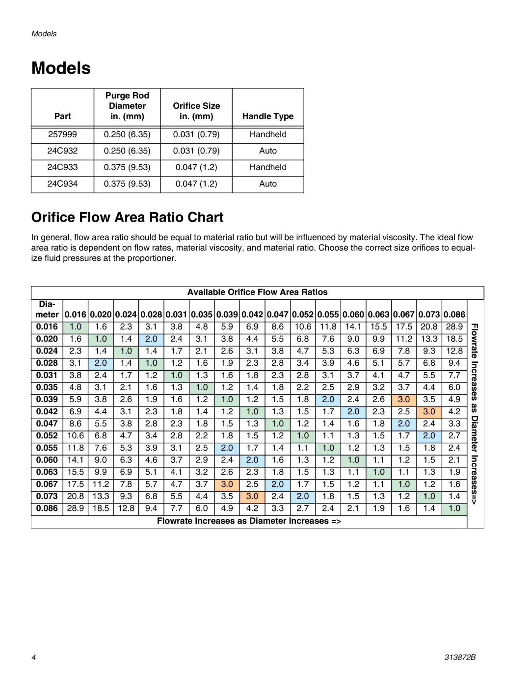
Models
| Purge Rod |
|
|
| Diameter | Orifice Size |
|
Part | in. (mm) | in. (mm) | Handle Type |
|
|
|
|
|
|
|
|
257999 | 0.250 (6.35) | 0.031 (0.79) | Handheld |
|
|
|
|
24C932 | 0.250 (6.35) | 0.031 (0.79) | Auto |
|
|
|
|
24C933 | 0.375 (9.53) | 0.047 (1.2) | Handheld |
|
|
|
|
24C934 | 0.375 (9.53) | 0.047 (1.2) | Auto |
|
|
|
|
Orifice Flow Area Ratio Chart
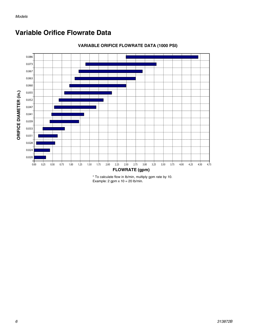
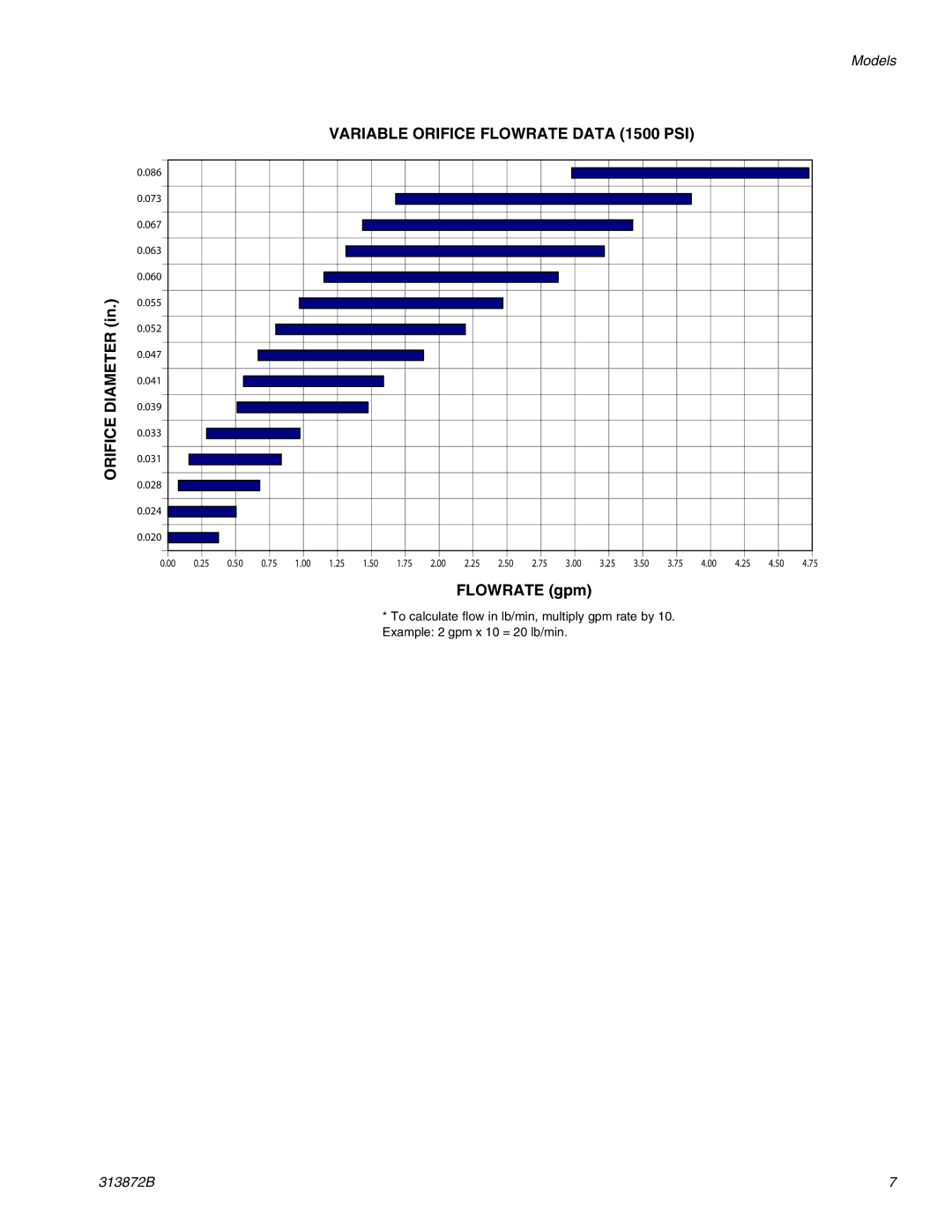
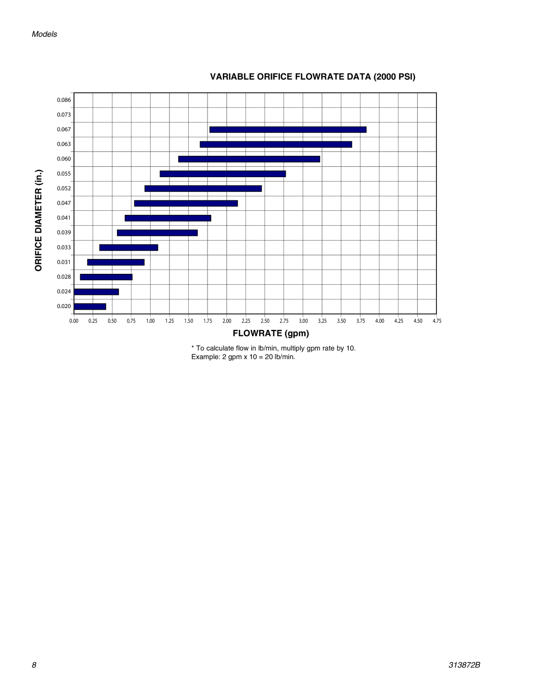
In general, flow area ratio should be equal to material ratio but will be influenced by material viscosity. The ideal flow area ratio is dependent on flow rates, material viscosity, and material ratio. Choose the correct size orifices to equal- ize fluid pressures at the proportioner.
Available Orifice Flow Area Ratios
Dia- |
|
|
|
|
|
|
|
|
|
|
|
|
|
|
|
|
| |
meter | 0.016 | 0.020 | 0.024 | 0.028 | 0.031 | 0.035 | 0.039 | 0.042 | 0.047 | 0.052 | 0.055 | 0.060 | 0.063 | 0.067 | 0.073 | 0.086 |
| |
|
|
|
|
|
|
|
|
|
|
|
|
|
|
|
|
| Flowrate | |
0.016 | 1.0 | 1.6 | 2.3 | 3.1 | 3.8 | 4.8 | 5.9 | 6.9 | 8.6 | 10.6 | 11.8 | 14.1 | 15.5 | 17.5 | 20.8 | 28.9 | ||
| ||||||||||||||||||
0.020 | 1.6 | 1.0 | 1.4 | 2.0 | 2.4 | 3.1 | 3.8 | 4.4 | 5.5 | 6.8 | 7.6 | 9.0 | 9.9 | 11.2 | 13.3 | 18.5 |
| |
0.024 | 2.3 | 1.4 | 1.0 | 1.4 | 1.7 | 2.1 | 2.6 | 3.1 | 3.8 | 4.7 | 5.3 | 6.3 | 6.9 | 7.8 | 9.3 | 12.8 |
| |
0.028 | 3.1 | 2.0 | 1.4 | 1.0 | 1.2 | 1.6 | 1.9 | 2.3 | 2.8 | 3.4 | 3.9 | 4.6 | 5.1 | 5.7 | 6.8 | 9.4 | Increases | |
0.031 | 3.8 | 2.4 | 1.7 | 1.2 | 1.0 | 1.3 | 1.6 | 1.8 | 2.3 | 2.8 | 3.1 | 3.7 | 4.1 | 4.7 | 5.5 | 7.7 | ||
| ||||||||||||||||||
0.035 | 4.8 | 3.1 | 2.1 | 1.6 | 1.3 | 1.0 | 1.2 | 1.4 | 1.8 | 2.2 | 2.5 | 2.9 | 3.2 | 3.7 | 4.4 | 6.0 |
| |
0.039 | 5.9 | 3.8 | 2.6 | 1.9 | 1.6 | 1.2 | 1.0 | 1.2 | 1.5 | 1.8 | 2.0 | 2.4 | 2.6 | 3.0 | 3.5 | 4.9 | as | |
0.042 | 6.9 | 4.4 | 3.1 | 2.3 | 1.8 | 1.4 | 1.2 | 1.0 | 1.3 | 1.5 | 1.7 | 2.0 | 2.3 | 2.5 | 3.0 | 4.2 | ||
Diameter | ||||||||||||||||||
0.055 | 11.8 | 7.6 | 5.3 | 3.9 | 3.1 | 2.5 | 2.0 | 1.7 | 1.4 | 1.1 | 1.0 | 1.2 | 1.3 | 1.5 | 1.8 | 2.4 | ||
0.047 | 8.6 | 5.5 | 3.8 | 2.8 | 2.3 | 1.8 | 1.5 | 1.3 | 1.0 | 1.2 | 1.4 | 1.6 | 1.8 | 2.0 | 2.4 | 3.3 |
| |
0.052 | 10.6 | 6.8 | 4.7 | 3.4 | 2.8 | 2.2 | 1.8 | 1.5 | 1.2 | 1.0 | 1.1 | 1.3 | 1.5 | 1.7 | 2.0 | 2.7 |
| |
|
|
|
|
|
|
|
|
|
|
|
|
|
|
|
|
| Increases=> | |
0.060 | 14.1 | 9.0 | 6.3 | 4.6 | 3.7 | 2.9 | 2.4 | 2.0 | 1.6 | 1.3 | 1.2 | 1.0 | 1.1 | 1.2 | 1.5 | 2.1 | ||
| ||||||||||||||||||
0.063 | 15.5 | 9.9 | 6.9 | 5.1 | 4.1 | 3.2 | 2.6 | 2.3 | 1.8 | 1.5 | 1.3 | 1.1 | 1.0 | 1.1 | 1.3 | 1.9 |
| |
0.067 | 17.5 | 11.2 | 7.8 | 5.7 | 4.7 | 3.7 | 3.0 | 2.5 | 2.0 | 1.7 | 1.5 | 1.2 | 1.1 | 1.0 | 1.2 | 1.6 |
| |
0.073 | 20.8 | 13.3 | 9.3 | 6.8 | 5.5 | 4.4 | 3.5 | 3.0 | 2.4 | 2.0 | 1.8 | 1.5 | 1.3 | 1.2 | 1.0 | 1.4 |
| |
0.086 | 28.9 | 18.5 | 12.8 | 9.4 | 7.7 | 6.0 | 4.9 | 4.2 | 3.3 | 2.7 | 2.4 | 2.1 | 1.9 | 1.6 | 1.4 | 1.0 |
| |
|
|
|
|
| Flowrate | Increases as Diameter Increases => |
|
|
|
|
|
| ||||||
|
|
|
|
|
|
|
|
|
|
|
|
|
|
|
|
|
| |
4 | 313872B |
