Carrier 48HE003---006, 48HJ004---007 installation instructions ECONOMI$ER IV Control Modes

Page 24

48HE,HJ

Supply Air Temperature (SAT) Sensor

The supply air temperature sensor is a 3 K thermistor located at the inlet of the indoor fan. (See Fig. 41.) This sensor is factory installed. The operating range of temperature measurement is 0° to 158_F. See Table 6 for sensor temperature/resistance values.

Table 6—Supply Air Sensor Temperature/

Resistance Values

TEMPERATURE (F)

RESISTANCE (ohms)


–58

200,250


–40

100,680


–22

53,010


–4

29,091

14


16,590

32


9,795

50


5,970

68


3,747

77


3,000

86


2,416

104


1,597

122


1,080

140


746

158


525

176


376

185


321

194


274

212


203

230


153

248


116

257


102

266


89

284


70

302


55


17 1/4”


DIVIDER

OUTSIDE

AIR

HOOD

CLEANABLE ALUMINUM FILTER

FILTER

BAROMETRIC RELIEF

FILTER CLIP

C06027

Fig. 35 ---Filter Installation

The temperature sensor looks like an eyelet terminal with wires running to it. The sensor is located in the “crimp end” and is sealed from moisture.

Outdoor Air Lockout Sensor

The Economi$er IV is equipped with an ambient temperature lockout switch located in the outdoor air stream which is used to lockout the compressors below a 42_F ambient temperature. (See Fig. 29.)

ECONOMI$ER IV CONTROL MODES

IMPORTANT: The optional EconoMi$er2 does not include a controller. The EconoMi$er2 is operated by a 4 to 20 mA signal from an existing field-supplied controller (such as PremierLinkcontrol). See Fig. 37 for wiring information.

Determine the EconoMi$er IV control mode before set up of the control. Some modes of operation may require different sensors. Refer to Table 7. The EconoMi$er IV is supplied from the factory with a supply-air temperature sensor and an outdoor- air temperature sensor. This allows for operation of the EconoMi$er IV with outdoor air dry bulb changeover control. Additional accessories can be added to allow for different types of changeover control and operation of the EconoMi$er IV and unit.

Table 7—Economi$er iv sensor usage


ECONOMI$ER IV WITH OUTDOOR AIR

APPLICATION


DRY BULB SENSOR


Accessories Required

Outdoor Air

None. The outdoor air dry bulb sensor

Dry Bulb


is factory installed.

Differential


CRTEMPSN002A00*

Dry Bulb


Single Enthalpy


HH57AC078

Differential


HH57AC078


and

Enthalpy


CRENTDIF004A00*


CO2 for DCV


Control using a


33ZCSENCO2

Wall-Mounted


CO2 Sensor


CO2 for DCV

33ZCSENCO2†


O


Control using a

and


CRCBDIOX005A00††

Duct-Mounted


R


33ZCASPCO2**


CO2 Sensor


*CRENTDIF004A00 and CRTEMPSN002A00 accessories are used on many different base units. As such, these kits may contain parts that will not be needed for installation.

2sensor.

**33ZCASPCO2 is an accessory aspirator box required for duct-mounted applications.† 33ZCSENCO2 is an accessory CO

††CRCBDIOX005A00 is an accessory that contains both 33ZCSENCO2 and 33ZCASPCO2 accessories.

Outdoor Dry Bulb Changeover

The standard controller is shipped from the factory configured for outdoor dry bulb changeover control. The outdoor-air and supply-air temperature sensors are included as standard. For this control mode, the outdoor temperature is compared to an adjustable set point selected on the control. If the outdoor-air temperature is above the set point, the EconoMi$er IV will adjust the outdoor-air dampers to minimum position. If the outdoor air temperature is below the set point, the position of the outdoor air dampers will be controlled to provide free cooling using outdoor air. When in this mode, the LED next to the free cooling set point potentiometer will be on. The changeover temperature set point is controlled by the free cooling set point potentiometer located on the control. (See Fig. 42.) The scale on the potentiometer is A, B, C, and D. See Fig. 43 for the corresponding temperature changeover values.

Differential Dry Bulb Control

For differential dry bulb control the standard outdoor dry bulb sensor is used in conjunction with an additional accessory dry bulb sensor (part number CRTEMPSN002A00). The accessory sensor must be mounted in the return airstream. (See Fig. 44.) Wiring is provided in the EconoMi$er IV wiring harness. (See Fig. 36.)

In this mode of operation, the outdoor-air temperature is compared to the return-air temperature and the lower temperature airstream is used for cooling. When using this mode of changeover control, turn the enthalpy setpoint potentiometer fully clockwise to the D setting. (See Fig. 42.)

24

Image 24
Contents Installation Instructions Electrical Shock HazardFIRE, Explosion Hazard Roof CurbAlternate Unit Support 48HE,HJ Install Flue Hood Property Damage HazardPositioning Unit Operating Dimensions Weight 48HE48HJ 48HJ004-007 Base Unit Dimensions 48HE003-006 Base Unit Dimensions Field power supply Field control wiringHeat anticipator settings Physical Data 48HJ Nominal CapacityHJE HJD Physical Data 48HE HEE HED Power Wiring Connections Electrical Data 48HE 48HE003---006Electrical Data 48HJ 38.2 242 208/230---3---60 187 254 12.4 Assembly HUMIDI-MIZERADAPTIVE Dehumidification SystemManual outdoor damper Convenience outletTypical Humidi-MiZer t Adaptive Dehumidification System Install the Supply Air Temperature SAT Sensor Outdoor Air Temperature Sensor OATInstall the Indoor Air Quality CO2 Sensor Enthalpy Sensors and ControlPremierLinkSensor Usage PremierLink ControllerPremierLinktController Installed Return Air Enthalphy Sensor EconoMi$er IV Component LocationsOutdoor Air Temperature OAT Sensor ECONOMI$ER IV Standard SensorsECONOMI$ER IV Control Modes EconoMi$er IV Wiring RUNExhaust Set Point Adjustment Differential Enthalphy ControlIndoor Air Quality IAQ Sensor Input Minimum Position Control ThermostatsDamper Movement Enthalpy Changeover Set Points Demand Controlled Ventilation DCVAdjust Evaporator-Fan Speed Dehumidification of Fresh Air with DCV ControlBelt drive motors CO2Sensor Standard Settings Belt Drive Motor Mounting48HJ Fan Rpm at Motor Pulley Setting With High-Static Motor Accessory static pressureEvaporator-Fan Motor Data Standard Motor Evaporator-Fan Motor Data High-Static Motors48HJ Outdoor Sound Power Total Unit 48HE Outdoor Sound Power Total UnitUnit ARI Octave Bands Rating AirflowRpm Bhp 11001200 1300Rpm Bhp Watts Rpm Bhp Watts Watts Rpm Bhp 12001600 1700Rpm Bhp Watts 1500 1642 2333 1704Watts Rpm Bhp 1800 26002700 2800Bhp Watts Rpm 2700 2800 2900 3000Bhp 600 Bhp Watts 900 Watts RpmWatts Rpm Bhp 900 1700 1800 1900 2000 Bhp Watts1900 2000 2100 2200 2300 2400 2500 800 350 904 438 999 535 1087 640 1169 753 913 569 1250 1500 1750 2000 2250 2500 2750 3000 Internal Wiring Refrigerant Service PortsUnit Preparation Gas PipingCooling Main BurnersHeating Safety Relief Ventilation Continuous FanOperating Sequence Cooling units without economizer Heating units without economizerDX Cooling Temperature Control Example Routine 3 OATSubcooling Mode Units with HUMIDI-MIZERADAPTIVE Dehumidification SystemNormal Design Operation Cleaning Evaporator CoilCondenser coil One-Row CoilsCondenser-Fan Adjustment High Pressure SwitchFilters Lubrication CompressorHUMIDI-MIZERSYSTEM Charging Cooling Charging Chart Standard 48HJ006 To USE Cooling Charging CHART, Standard Unit Flue Gas Passageways Combustion-Air BlowerLimit Switch LED Error Code DescriptionRemoval and Replacement of GAS Train See Burner IgnitionReplacement Parts LOW HeatOFM Unit Troubleshooting Economi$er IV TroubleshootingDcv demand controlled ventilation and power exhaust Economi$er IV troubleshooting completionLED Error Code Service Analysis Symptom Cause RemedyComponent Damage Hazard LED OFFHeating Service Analysis Problem Cause RemedyCooling Service Analysis EconoMi$er IV Input/Output Logic Inputs OutputsSTART-UP Checklist

48HJ004---007, 48HE003---006 specifications

Carrier has long been a trusted name in the HVAC industry, and its models 48HJ004---007 and 48HE003---006 continue that legacy, offering efficient, reliable climate control solutions. These models are designed for different applications, ensuring optimal performance in a variety of environments.

The 48HJ series features advanced rooftop units that are ideal for commercial settings. They come equipped with high-efficiency scroll compressors that provide superior cooling and heating capabilities. This series is noted for its compact design, allowing for easy installation on rooftops or other constrained spaces. The units offer variable capacity operation, which enables them to efficiently meet varying heating and cooling demands without unnecessary energy consumption.

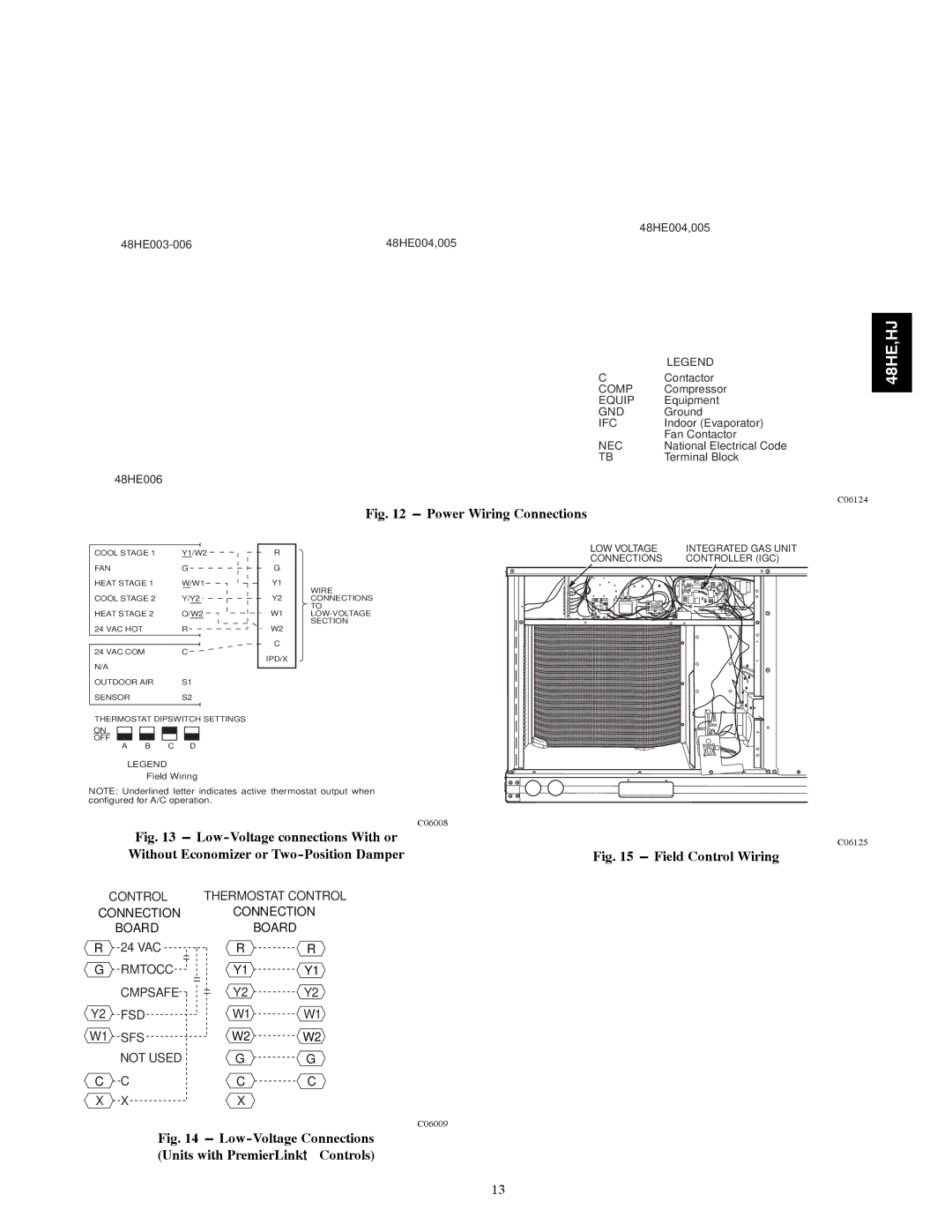
One of the standout features of the 48HJ series is its use of advanced microprocessor controls. This technology allows for precise temperature management and system diagnostics, enhancing the ease of operation while ensuring maximum comfort. Additionally, the series supports advanced connectivity options, enabling integration with building management systems. This allows for remote monitoring and control, making it easier for facility managers to keep track of performance and energy usage.

On the other hand, the 48HE series specializes in high-efficiency heating and cooling performance. These units are designed for larger commercial spaces and come with robust features for enhanced durability and efficiency. Like the 48HJ series, the 48HE models utilize scroll compressors and are equipped with a high-efficiency fan setup for improved airflow and reduced noise levels.

The 48HE also includes an innovative heat pump option, which allows the system to reverse the cooling process to provide heating, making it versatile across different seasonal demands. Both series are designed with eco-friendly refrigerants that comply with the latest environmental regulations, ensuring a minimized ecological footprint.

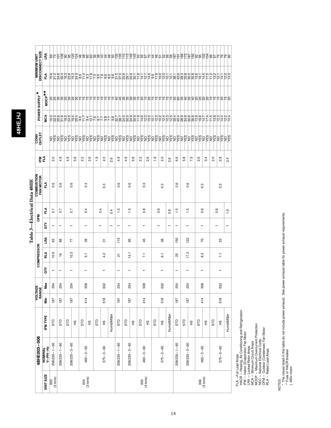
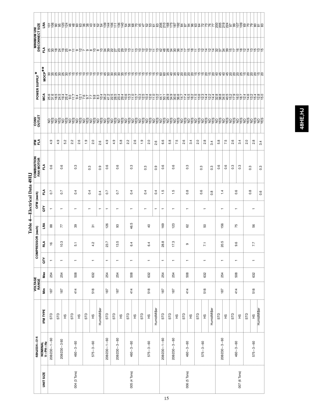
In terms of energy efficiency, both the 48HJ and 48HE series hold impressive SEER and EER ratings, contributing to reduced operational costs over time. The units are also built with durable, corrosion-resistant materials, ensuring longevity and low maintenance needs.

In conclusion, Carrier 48HJ004---007 and 48HE003---006 models are designed with cutting-edge technology, energy efficiency, and flexibility in mind. Their robust features make them ideal choices for commercial applications, providing reliable comfort and operational excellence. Whether for cooling or heating, these systems stand out in performance and sustainability, earning Carrier's reputation as a leader in the HVAC market.