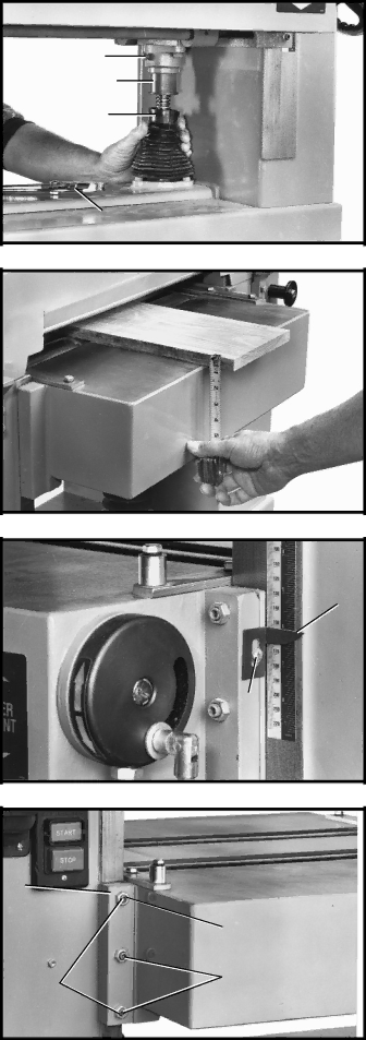
5.If the table is not parallel to the cutterhead, lower boot
(B) Fig. 51, which is located underneath the table. NOTE: Table elevating handwheel must be unlocked when making this adjustment.
6.Loosen lock screw (C) Fig. 51, and with large pliers (D) turn adjustment sleeve (E) as necessary until table is paralell with the cutterhead. Tighten lock screw (C) after adjustment is made and replace boot (B). NOTE: The same adjustment can also be made on the other side of the planer if necessary.
C
E
B
D
Fig. 51
ADJUSTING TABLE HEIGHT SCALE
The table height scale indicates the distance the table is from the cutting circle (depth of cut). To check and adjust the pointer, proceed as follows:
1.Run a piece of wood through the planer and stop the machine.
2.Measure the thickness of the planed end of the stock as shown in Fig. 52. If an adjustment is nec- essary, loosen screw (A) Fig. 53, adjust pointer (B) and retighten screw (A).
ADJUSTING TABLE GIBS
In the unlikely event of the table developing unwanted movement during planing operations, the table can be checked and adjusted as follows:
1. DISCONNECT MACHINE FROM POWER SOURCE.
2.With the table in the locked position, and with a feel- er gage, measure the gap between table gib (A) Fig. 54 and table bracket (B). When set correctly the gap should be .005 .
3.If an adjustment is necessary, loosen three locknuts (C), and turn three adjustment screws (D) Fig. 54, as necessary to set the correct gap.
4.Check and adjust the gap on the other side of the table in the same manner. Tighten six locknuts, three of which are shown at (C) Fig. 54, after adjustment is made.
5.Raise and lower the table to its fullest range and check to see if the table moves up and down with- out binding.
Fig. 52
B
A
Fig. 53
![]() A
A
B
C
D ![]() C
C
Fig. 54
22