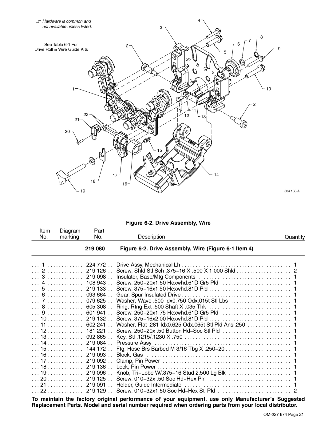
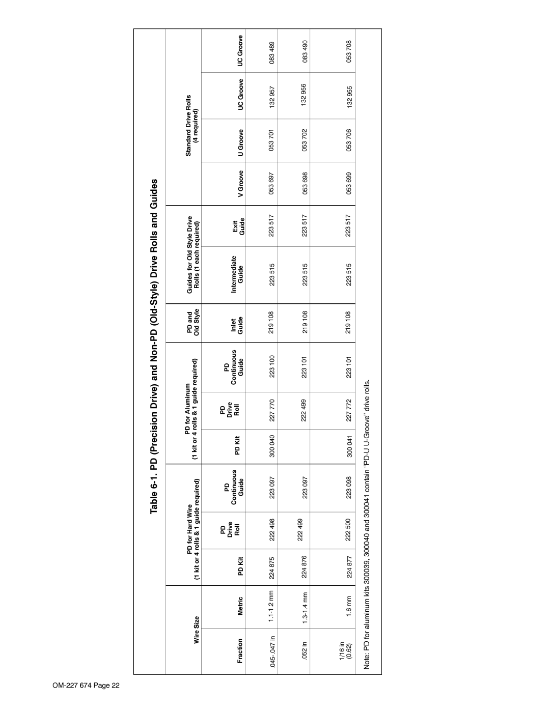
Miller Electric AA40GBU manual Routine Maintenance, Brush Inspection And Replacement

Page 21

SECTION 4 − MAINTENANCE AND TROUBLESHOOTING

4-1. Routine Maintenance

Y Disconnect power before maintaining.

n = Check

Z = Change

~ = Clean

l = Replace

Reference

* To be done by Factory Authorized Service Agent


Every

l Unreadable Labels

~ Weld Terminals

nl Weld Cables

l Cracked Parts

3

Months


n Gun Cable

n Gas Hose And Fittings


Every


6


Months

Or


~ Inside Of Unit

~ Drive Rolls


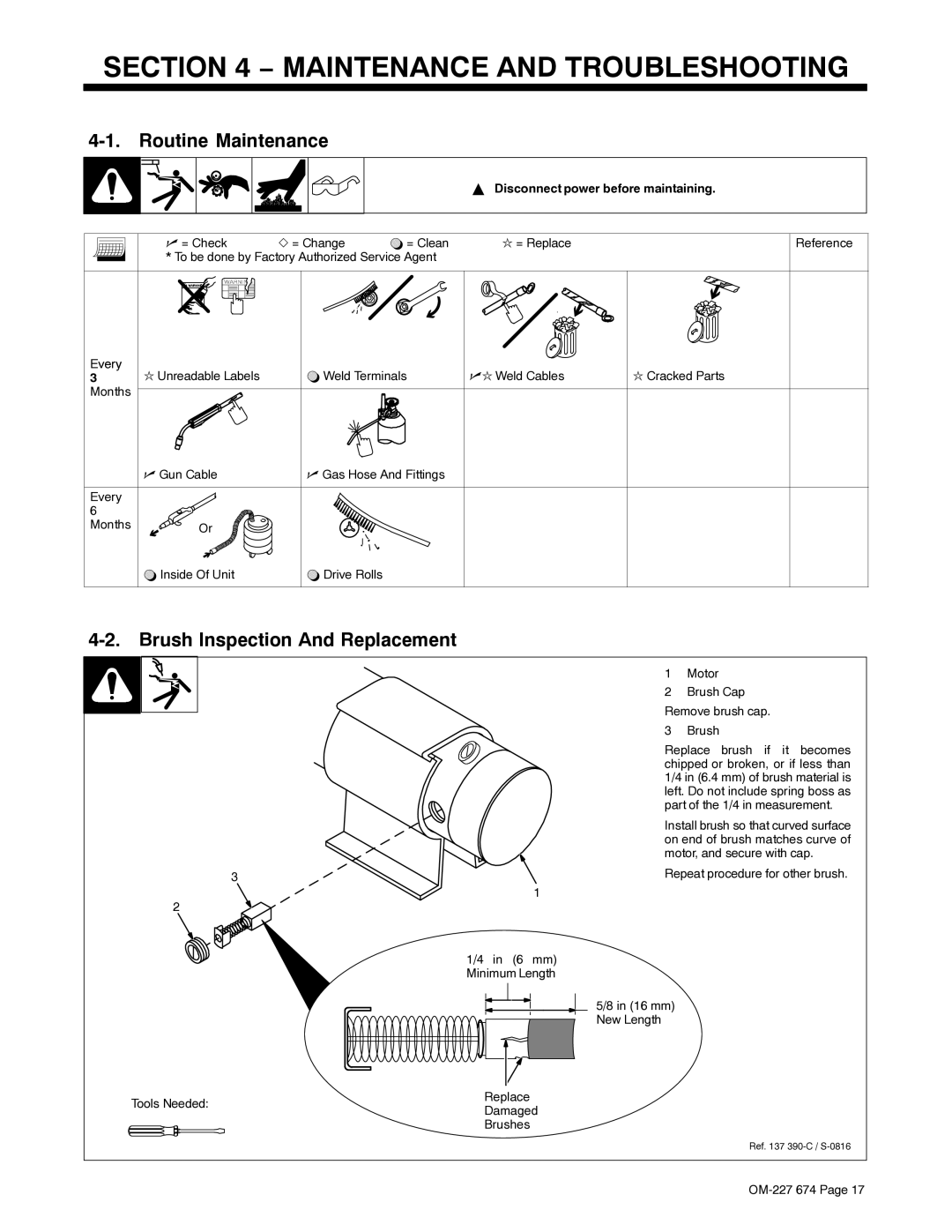
4-2. Brush Inspection And Replacement

1 Motor

2 Brush Cap Remove brush cap.

3 Brush

Replace brush if it becomes chipped or broken, or if less than 1/4 in (6.4 mm) of brush material is left. Do not include spring boss as part of the 1/4 in measurement.

Install brush so that curved surface on end of brush matches curve of motor, and secure with cap.

3

Repeat procedure for other brush.

1

2

1/4 in (6 mm) Minimum Length

5/8 in (16 mm) New Length

Tools Needed:

Replace

Damaged


Brushes

Ref. 137 390-C / S-0816

OM-227 674 Page 17

Image 21
Contents Processes OM-227 674BDescription File Advanced Manufacturing SystemsFrom Miller to You Table of Contents Page Marks a special safety message Symbol UsageArc Welding Hazards Electric Shock can killWelding can cause fire or explosion ARC Rays can burn eyes and skinFlying Metal can injure eyes Buildup of GAS can injure or killCalifornia Proposition 65 Warnings Principal Safety Standards EMF InformationAbout Pacemakers UNE Décharge Électrique peut entraîner la mort LES Fumées ET LES GAZ peuvent être dangereuxIndique un message de sécurité particulier Incendie ou une explosion LE Soudage peut provoquer unDES Particules Volantes peuvent blesser les yeux DES Pièces Chaudes peuvent provoquer des brûlures gravesLA Chute DE L’APPAREIL peut blesser Risque D’INCENDIE OU D’EXPLO’EMPLOI Excessif peut SUR DES Organes Mobiles peuvent provoquer des blessuresEn ce qui concerne les stimulateurs cardiaques Principales normes de sécuritéSpecifications Overall Dimensions And Mounting Hole LayoutAdapter Bracket Installation Installing Drive RollsTypical Equipment Location RemovalInstalling PD continuous wire guides with PD drive rolls Installing PD Continuous Wire GuidesInstalling wire guides with non- PD old-style drive rolls Installing Non-PD Old Style Wire GuidesInstalling Welding Gun Installing gun with Accu-Mate connectionInstalling gun without Accu- Mate connection Drive motor must be isolated from weld potential Mounting Motor And Connecting Gas Hose And Weld CablePlug Connections Powerjog Threading Welding Wire And Adjusting Pressure Drive SettingRoutine Maintenance Brush Inspection And ReplacementDisconnect power before maintaining Circuit Diagram For AA40GBU/Gas Box Left Hand Troubleshooting− Parts List Drive Assembly, Wire 219 Drive Assembly, Wire -1ItemGuides for Old Style Drive Support ServiceMiller Electric Mfg. Co Owner’s Record