Repair | P 2/ 13 |
|
CAUTION: Repair the machine in accordance with “Instruction manual” or “Safety instructions”.
[1] NECESSARY REPAIRING TOOLS
Code No. | Description | Use for |
1R041 | Vise plate | Protecting parts when holding in vise |
1R034 | Bearing setting plate 12.2 | Installing Ball bearing 6900LLB |
1R145 | Loosening/tightening M5x10 Torx countersunk head screw | |
1R173 | Retaining ring R pliers | Removing/installing Retaining ring |
1R219 | Torque wrench shaft | Installing Bearing retainer |
1R220 | Ratchet head 9.5 (for 1R219) | Installing Bearing retainer |
1R222 | Socket adapter | Installing Bearing retainer |
1R269 | Bearing extractor | Removing Ball bearing 6900LLB |
1R288 | Screwdriver Magnetizer | Magnetizing Screwdriver for removing Steel balls |
1R291 | Retaining ring S and R pliers | Removing/installing Retaining ring |
1R314 | Torx bit | Loosening/tightening M5x10 Torx countersunk head screw |
Socket | Installing Bearing retainer | |
Torque adjust tool | Disassembling Clutch assembly | |
Hex wrench 6 (flats width: 6mm) | Loosening/tightening Adjust ring complete |
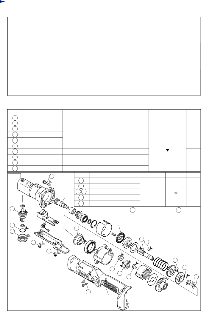
[2] LUBRICATIONS/ GLUING
Apply Makita grease N.No.2/ Loctite 603 to the portions designated by arrows.
Item No. | Description | Portion to lubricate | Lubricant | Amount |
13 | Spindle | Left hand where M12 Lock nut contacts |
| a little |
28 | Spindle A complete | Gear teeth that engages with Spiral bevel gear 9 |
| 2g |
14Steel ball 5.0 (3pcs.)
17 | Steel ball 4 (3pcs.) | Whole surface |
|
|
|
| a little | |
19 | Steel ball 3 (13pcs.) |
|
|
|
| |||
|
|
|
| Makita grease N.No.2 |
| |||
35 | O ring 14 |
|
|
|
|
| ||
37 | Carrier complete B | Three shaft pins |
|
|
|
|
| |
40 | Spur gear 18 (3pcs.) | Gear teeth |
|
|
|
| 2g in | |
41 | Spur gear 9 complete A Gear teeth and three shaft pins |
|
|
| total | |||
42 | Spur gear 18 (3pcs.) | Gear teeth |
|
|
|
|
| |
Fig. 1 | 2 |
| Item No. | Description | Portion to glue | Adhesive | Amount | |
|
|
| 2 | M4x22 Pan head screw (4pcs.) |
|
|
| |
|
| Spiral | 21 | Torx C.S.H. screw M5x10 |
|
| Loctite 603 |
|
|
| bevel | 25 26 | M4x8 Pan head screw |
| Thread | a little | |
|
| gear 9 | 36 | Bearing retainer |
|
|
|
|
|
|
|
|
|
|
| ||
|
|
| 86 | M3x20 Pan head screw (7pcs.) |
|
|
| |
28 |
|
|
| Note: Part No. for 40 | is different from that for 42 . |
| ||
35 |
|
|
| M12 Lock nut |
|
|
|
|
|
| 37 |
|
|
|
|
| |
36 |
|
|
|
|
|
|
| |
|
|
|
|
|
|
|
| |
| 25 |
|
|
| 13 | 14 |
|
|
| 26 |
|
|
|
|
|
|
|
|
|
|
|
|
|
| 17 |
|
|
|
|
| 40 |
|
| 19 |
|
|
|
|
|
|
|
|
| |
|
|
|
| 41 |
|
|
| 21 |
|
|
|
| 42 |
|
|
| |
|
|
| 86 |
|
|
|
|
|
Housing L