CONTROL BOARD FUNCTIONS
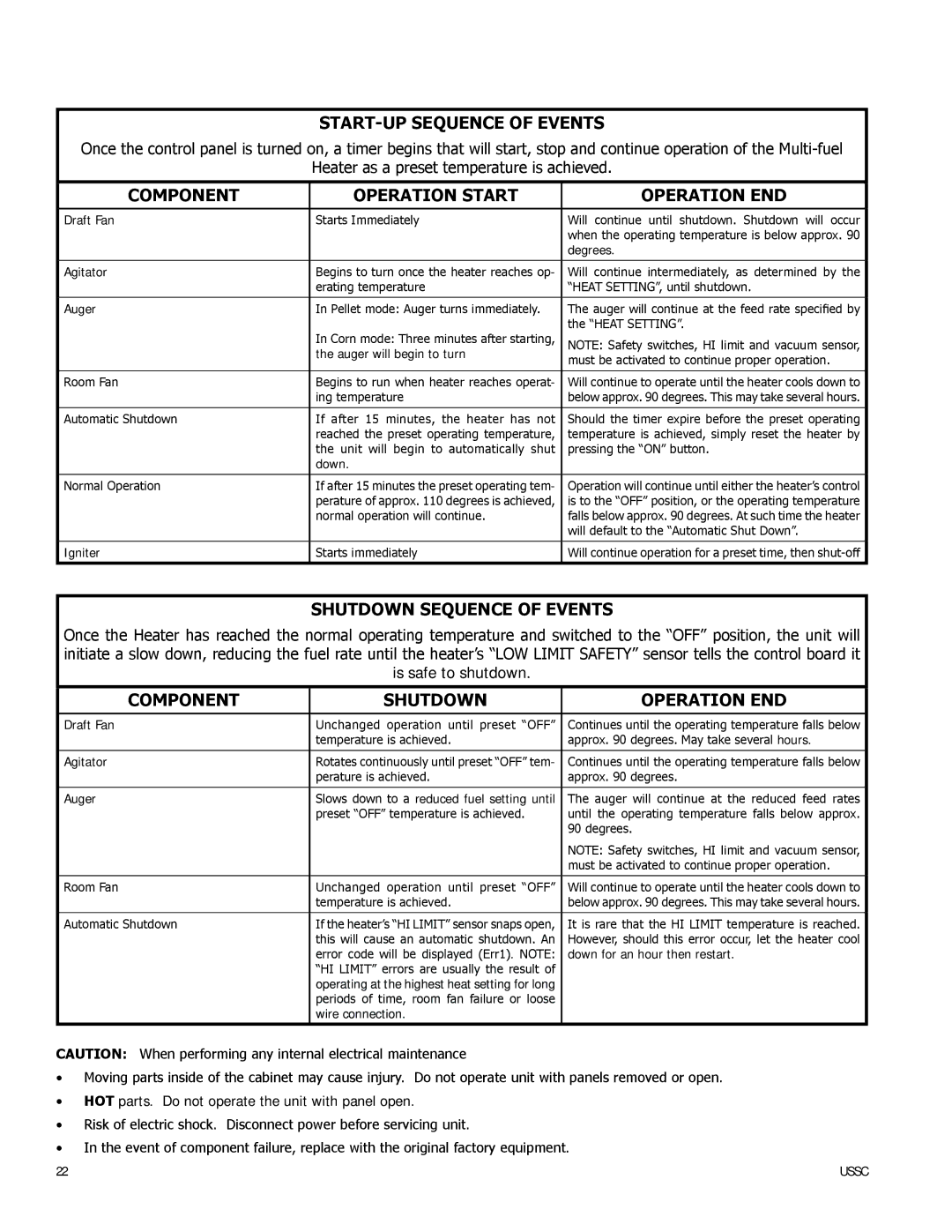
START-UP SEQUENCE OF EVENTS
Once the control panel is turned on, a timer begins that will start, stop and continue operation of the
Heater as a preset temperature is achieved.
COMPONENT | OPERATION START | OPERATION END |
|
|
|
Draft Fan | Starts Immediately | Will continue until shutdown. Shutdown will occur |
|
| when the operating temperature is below approx. 90 |
|
| degrees. |
|
|
|
Agitator | Begins to turn once the heater reaches op- | Will continue intermediately, as determined by the |
| erating temperature | “HEAT SETTING”, until shutdown. |
|
|
|
Auger | In Pellet mode: Auger turns immediately. | The auger will continue at the feed rate specified by |
| In Corn mode: Three minutes after starting, | the “HEAT SETTING”. |
| NOTE: Safety switches, HI limit and vacuum sensor, | |
| the auger will begin to turn | must be activated to continue proper operation. |
|
| |
|
|
|
Room Fan | Begins to run when heater reaches operat- | Will continue to operate until the heater cools down to |
| ing temperature | below approx. 90 degrees. This may take several hours. |
|
|
|
Automatic Shutdown | If after 15 minutes, the heater has not | Should the timer expire before the preset operating |
| reached the preset operating temperature, | temperature is achieved, simply reset the heater by |
| the unit will begin to automatically shut | pressing the “ON” button. |
| down. |
|
|
|
|
Normal Operation | If after 15 minutes the preset operating tem- | Operation will continue until either the heater’s control |
| perature of approx. 110 degrees is achieved, | is to the “OFF” position, or the operating temperature |
| normal operation will continue. | falls below approx. 90 degrees. At such time the heater |
|
| will default to the “Automatic Shut Down”. |
|
|
|
Igniter | Starts immediately | Will continue operation for a preset time, then |
SHUTDOWN SEQUENCE OF EVENTS
Once the Heater has reached the normal operating temperature and switched to the “OFF” position, the unit will initiate a slow down, reducing the fuel rate until the heater’s “LOW LIMIT SAFETY” sensor tells the control board it is safe to shutdown.
COMPONENT | SHUTDOWN | OPERATION END |
|
|
|
Draft Fan | Unchanged operation until preset “OFF” | Continues until the operating temperature falls below |
| temperature is achieved. | approx. 90 degrees. May take several hours. |
|
|
|
Agitator | Rotates continuously until preset “OFF” tem- | Continues until the operating temperature falls below |
| perature is achieved. | approx. 90 degrees. |
|
|
|
Auger | Slows down to a reduced fuel setting until | The auger will continue at the reduced feed rates |
| preset “OFF” temperature is achieved. | until the operating temperature falls below approx. |
|
| 90 degrees. |
|
| NOTE: Safety switches, HI limit and vacuum sensor, |
|
| must be activated to continue proper operation. |
|
|
|
Room Fan | Unchanged operation until preset “OFF” | Will continue to operate until the heater cools down to |
| temperature is achieved. | below approx. 90 degrees. This may take several hours. |
|
|
|
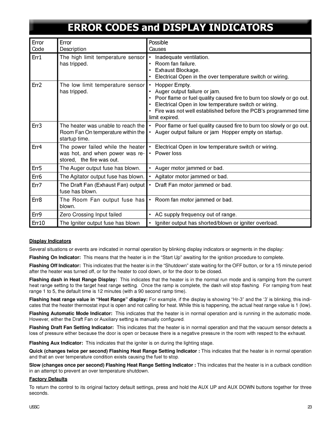
Automatic Shutdown | If the heater’s “HI LIMIT” sensor snaps open, | It is rare that the HI LIMIT temperature is reached. |
| this will cause an automatic shutdown. An | However, should this error occur, let the heater cool |
| error code will be displayed (Err1). NOTE: | down for an hour then restart. |
| “HI LIMIT” errors are usually the result of |
|
| operating at the highest heat setting for long |
|
| periods of time, room fan failure or loose |
|
| wire connection. |
|
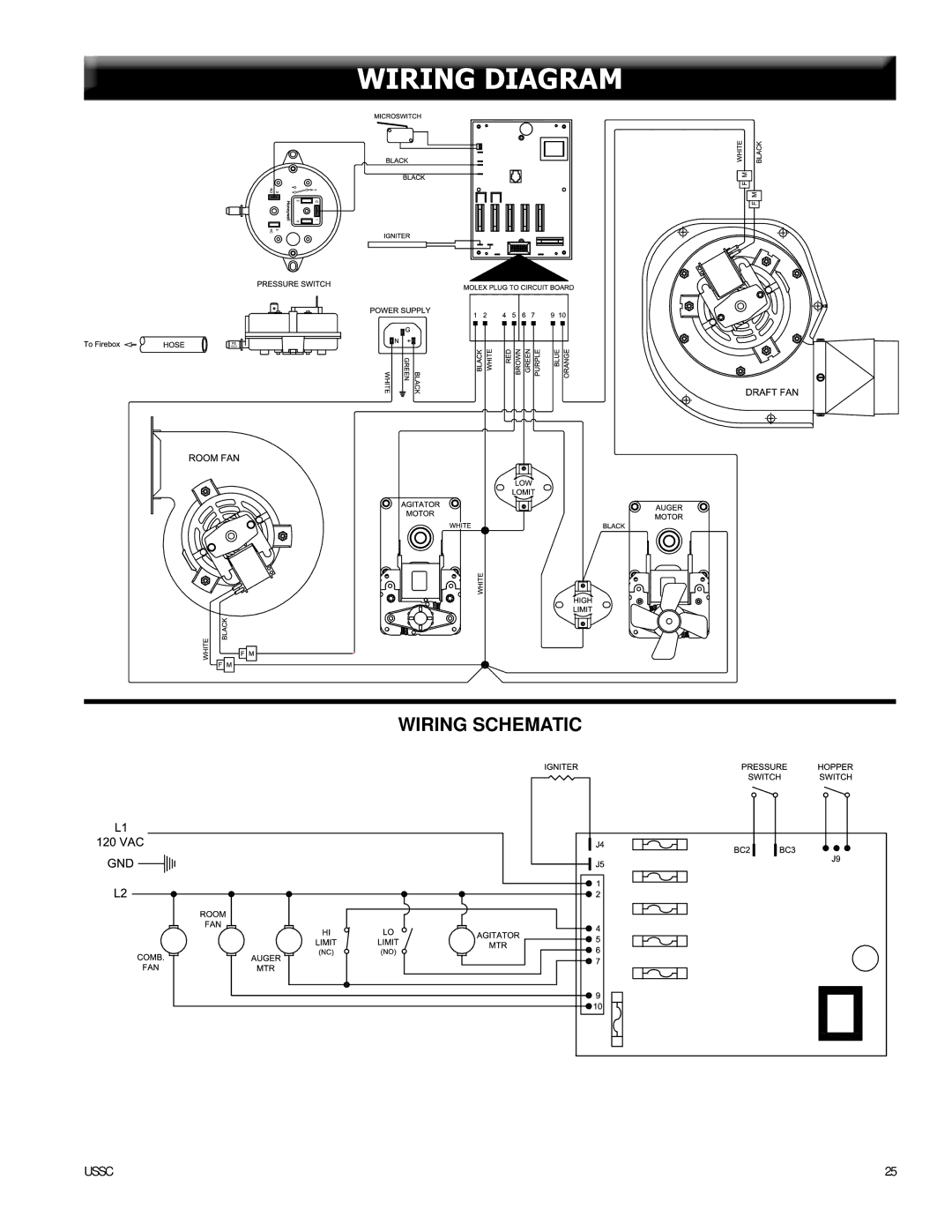
CAUTION: When performing any internal electrical maintenance
•Moving parts inside of the cabinet may cause injury. Do not operate unit with panels removed or open.
•HOT parts. Do not operate the unit with panel open.
•Risk of electric shock. Disconnect power before servicing unit.
•In the event of component failure, replace with the original factory equipment.
22 | USSC |
