Memory Timing
| BIOS SETUP UTILITY |
|
| |
OC Tweaker |
|
|
| |
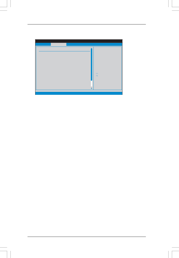
Memory Timing |
|
|
| |
Power Down Enable | [Disabled] |
|
| |
Bank Interleaving | [Auto] |
|
| |
Channel Interleaving | [Hash 2] |
|
| |
CAS Latency (CL) | [Auto] |
|
| |
TRCD | [Auto] |
|
| |
TRP | [Auto] |
|
| |
TRAS | [Auto] |
|
| |
Command Rate | [Auto] |
|
| |
TRC | [Auto] |
| Select Screen | |
TRTP | [Auto] |
| ||
| Select Item | |||
TWR | [Auto] |
| ||
+- | Change Option | |||
TRFC | [Auto] | |||
F1 | General Help | |||
TRRD | [Auto] | |||
F9 | Load Defaults | |||
TWTR | [Auto] | |||
F10 | Save and Exit | |||
TRTP | [Auto] | |||
ESC | Exit | |||
TFAW | [Auto] | |||
|
| |||
v02.54 (C) Copyright | ||||
Power Down Enable
Use this item to enable or disable DDR power down mode.
Bank Interleaving
Interleaving allows memory accesses to be spread out over banks on the same node, or accross nodes, decreasing access contention.
Channel Interleaving
It allows you to enable Channel Memory Interleaving. Configuration options: [Disabled], [Address bits 6], [Address bits 12], [HASH 1] and [HASH 2]. The default value is [HASH 2].
CAS Latency (CL)
Use this item to adjust the means of memory accessing. The default value is [Auto].
TRCD
Use this to adjust TRCD values. The default value is [Auto].
TRP
Use this to adjust TRP values. The default value is [Auto].
TRAS
Use this to adjust TRAS values. The default value is [Auto].
Command Rate
Use this item to change Command Rate Auto/Manual setting. Min: 1N.
Max: 2N. The default is [Auto].
TRC
Use this to adjust TRC values. The default value is [Auto].
TRTP
Use this to adjust TRTP values. The default value is [Auto].
TWR
Use this to adjust TWR values. The default value is [Auto].
TRFC
Use this to adjust TRFC values. The default value is [Auto].
39