ASRock 775S61 manual Installation of Memory Modules Dimm, Notch break

Page 13

2.5 Installation of Memory Modules (DIMM)

775S61 motherboard provides three 184-pin DDR (Double Data Rate) DIMM slots.

Please make sure to disconnect power supply before adding or removing DIMMs or the system components.

Step 1. Unlock a DIMM slot by pressing the retaining clips outward.

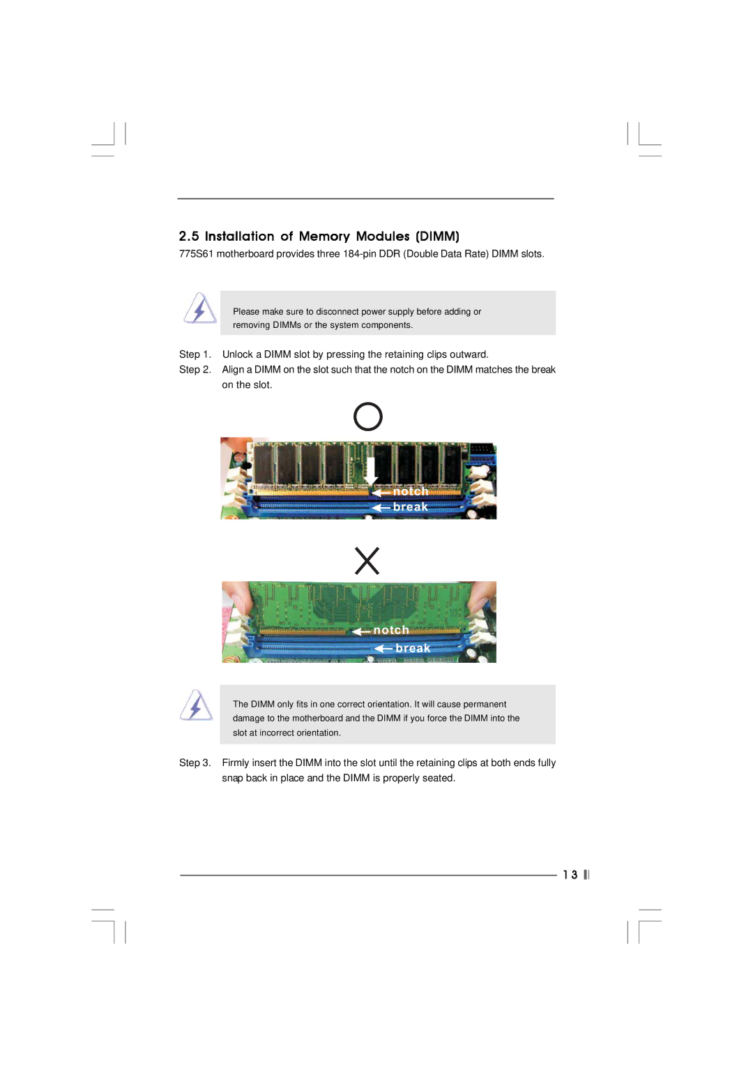
Step 2. Align a DIMM on the slot such that the notch on the DIMM matches the break on the slot.

notch break

notch break

The DIMM only fits in one correct orientation. It will cause permanent damage to the motherboard and the DIMM if you force the DIMM into the slot at incorrect orientation.

Step 3. Firmly insert the DIMM into the slot until the retaining clips at both ends fully snap back in place and the DIMM is properly seated.

1 3

Image 13 Contents
775S61 Disclaimer Copyright NoticeContents Introduction Package ContentsCPU SpecificationsVGA IDEMicrosoft Windows 98SE / ME / 2000 / XP compliant BiosMotherboard Layout 22.9cm 9.0ASRock I/OTM Pre-installation Precautions InstallationScrew Holes CPU Installation Page Installation of CPU Fan and Heatsink Notch break Installation of Memory Modules DimmExpansion Slots PCI, AMR, and AGP Slots Installing an expansion cardPS2USBPWR1 Jumpers SetupIDE2 Onboard Headers and ConnectorsFront panel audio connector Bios Setup Utility Bios SetupBios Menu Bar ESC Main MenuAuto TypeAdvanced, Security, Power, Boot, and Exit Menus Software Support Advanced Bios Setup Menu Appendix Advanced Bios Setup64MB Chipset ConfigurationPage Peripheral Configuration Resource ConfigurationRPM Enter Security Setup MenuPower Off Power Setup MenuEnabled Boot Setup MenuExit Menu
Related manuals
Manual 31 pages 9.58 Kb