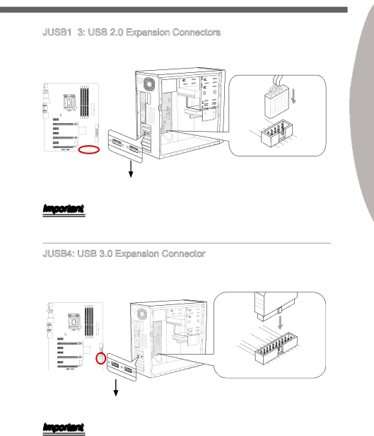
JUSB1~3: USB 2.0 Expansion Connectors
This connector is designed for connecting
|
|
|
| 10. |
|
|
|
|
|
|
|
|
|
| ||
|
| 6 | 8 |
|
|
|
|
|
|
|
|
|
|
|
| |
. |
| . NC |
|
|
|
|
|
|
|
|
|
| ||||
|
| USB1Ground |
|
|
|
|
|
|
|
|
|
| ||||
4 |
| . |
|
|
|
|
|
|
|
|
|
|
|
| ||
| . |
|
|
| + |
|
|
|
|
|
|
|
|
|
| |
VCUSB1 |
|
|
|
|
|
|
|
|
|
|
| |||||
2 |
|
|
|
|
|
|
|
|
|
|
|
|
|
|
|
|
|
| C |
| - |
|
|
|
|
|
|
|
|
|
|
| |
|
|
|
|
|
|
|
|
|
|
|
| 9 |
|
|
| |
|
|
|
|
|
|
|
| 5 | 7 |
| . |
|
| |||
|
|
|
|
|
|
|
|
| . No | Pi | ||||||
|
|
|
|
|
|
| 3 . |
|
|
|
| |||||
|
|
|
|
|
| 1 |
| . | USB0Ground | n | ||||||
|
|
|
|
|
| . |
|
| ||||||||
|
|
|
|
|
| VCUSB0 | - | + |
| |||||||
|
|
|
|
|
|
|
| C |
|
|
|
|
| |||
* The MB layout in this figure is for reference only. USB 2.0 Bracket (optional)
Important
Note that the VCC and GND pins must be connected correctly to avoid possible dam- age.
JUSB4: USB 3.0 Expansion Connector
The USB 3.0 port is backwards compatible with USB 2.0 devices. It supports data trans- fer rates up to 5Gbits/s (SuperSpeed).
Chapter 1
11
|
|
|
|
|
|
|
|
|
| 20. |
|
|
|
| |||
|
|
|
|
|
|
| 19. |
| N | P | |||||||
|
|
|
|
| 18. |
|
|
|
|
| |||||||
|
|
|
| 16.. |
|
| Power |
| n | ||||||||
|
|
|
| 17 |
|
| USB3_ |
| i | ||||||||
|
| 15. |
|
|
|
|
| ||||||||||
14 |
|
|
| USB3 |
|
|
| R |
| ||||||||
13. | . | USB3Ground | _ | X |
| ||||||||||||
|
|
|
|
|
|
|
|
|
|
|
|
| X | ||||
12. |
|
| USB3 |
|
|
|
|
|
|
|
| R |
| _ | |||
|
|
|
| _ |
|
|
|
|
|
|
| DDN | |||||
| Ground |
| TX |
|
|
|
| C |
|
|
| P | |||||
USUSB2 |
| _ |
| TX | _ | _ |
| ||||||||||
|
|
|
|
| _ |
|
| ||||||||||
. |
|
|
|
|
|
|
|
|
|
|
|
|
|
| |||
B | . | . |
|
|
|
|
| C |
|
| DN | ||||||
|
| - |
|
|
|
|
|
|
| _ |
| ||||||
| 2 | 0 |
|
|
|
|
|
|
|
|
|
|
| ||||
|
|
| 0 |
|
|
|
|
|
|
|
|
| D |
|
|
| |
|
|
|
| + |
|
|
|
|
|
|
|
|
| P |
|
| |
|
|
|
|
|
|
|
|
|
|
|
|
|
| 1 |
|
|
|
|
|
|
|
|
|
|
|
|
|
|
|
|
| 3 |
| . |
|
|
|
|
| ||
|
|
|
|
|
|
|
|
|
|
| . Po |
|
|
|
|
| ||||
|
|
|
|
|
|
|
|
|
|
|
| 2 |
|
|
|
|
|
|
| |
|
|
|
|
|
|
|
|
| 4 |
| . U |
| we |
|
|
| ||||
|
|
|
|
|
|
| 5 |
| . |
|
| SB3 |
| r |
| |||||
|
|
|
|
| 6 |
|
|
|
| SB3 |
|
|
|
| ||||||
|
|
| 8 |
|
|
|
|
|
|
|
|
| X |
|
| |||||
|
|
|
|
|
| . | . |
|
|
|
|
| _ | _ |
|
| ||||
|
|
|
| 7 |
| U |
|
|
|
|
|
|
|
| R |
| X | |||
|
|
|
| . |
| SB3 |
|
|
|
|
|
|
| _ | ||||||
| 9 |
|
|
|
|
| TX |
|
| C |
| D DN | ||||||||
| . |
| SB2Ground |
|
|
| _ |
| ||||||||||||
1 |
|
| . |
|
|
|
|
|
|
|
| _ |
|
|
| P | ||||
| U | U |
|
|
|
|
|
| _ |
| TX |
|
|
|
|
| ||||
0 | . |
|
|
|
|
|
|
|
| _ |
|
|
|
| ||||||
| SB2 . |
|
|
|
| _ | _ |
|
| |||||||||||
|
|
|
|
|
|
|
|
|
|
| ||||||||||
| Ground |
|
| 0 |
|
|
| C |
| P |
|
| ||||||||
|
|
|
|
| . |
|
|
|
|
| DN |
| ||||||||
|
|
|
|
|
| 0 |
|
| - |
|
|
| _ |
|
| |||||
|
|
|
|
|
|
| + |
|
|
|
|
|
| D |
|
|
| |||
* The MB layout in this figure is for reference only.
USB 3.0 Bracket (optional)
Important
•Note that the VCC and GND pins must be connected correctly to avoid possible damage.
•To use a USB 3.0 device, you must connect the device to a USB 3.0 port through an optional USB 3.0 compliant cable.