MS-6763 M-ATX Mainboard
Please refer to the following table for detailed
DIMM1 (CH A) | DIMM2 (CH A) | DIMM3 (CH B) | DIMM4 (CH B) | System Density |
128MB~1GB |
| 128MB~1GB |
| 256MB~2GB |
128MB~1GB |
|
| 128MB~1GB | 256MB~2GB |
| 128MB~1GB | 128MB~1GB |
| 256MB~2GB |
| 128MB~1GB |
| 128MB~1GB | 256MB~2GB |
128MB~1GB | 128MB~1GB | 128MB~1GB |
| 384MB~3GB |
128MB~1GB | 128MB~1GB |
| 128MB~1GB | 384MB~3GB |
128MB~1GB |
| 128MB~1GB | 128MB~1GB | 384MB~3GB |
| 128MB~1GB | 128MB~1GB | 128MB~1GB | 384MB~3GB |
128MB~1GB | 128MB~1GB | 128MB~1GB | 128MB~1GB | 512MB~4GB |
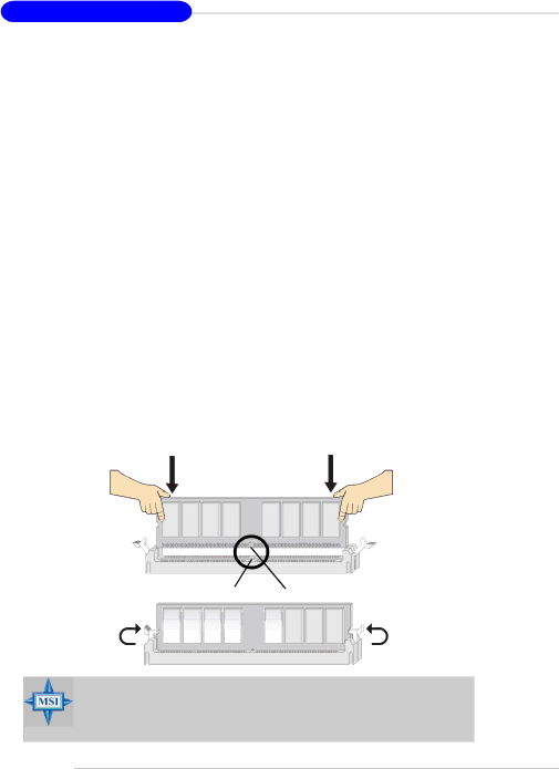
Installing DDR Modules
1.The DDR DIMM has only one notch on the center of module. The mod- ule will only fit in the right orientation.
2.Insert the DIMM memory module vertically into the DIMM slot. Then push it in until the golden finger on the memory module is deeply in- serted in the socket.
3.The plastic clip at each side of the DIMM slot will automatically close.
Volt Notch
MSI Reminds You...
You can barely see the golden finger if the module is properly inserted in the socket.