MSI 865GM3 manual Getting Help, Main Menu, Sub-Menu, General Help F1

Page 42

BIOS Setup

Getting Help

After entering the Setup menu, the first menu you will see is the Main Menu.

Main Menu

The main menu lists the setup functions you can make changes to. You can use the arrow keys ( ↑↓ ) to select the item. The on-line description of the highlighted setup function is displayed at the bottom of the screen.

Sub-Menu

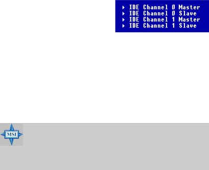
If you find a right pointer symbol (as shown in the right view) appears to the left of certain fields that means a

sub-menu can be launched from this field.

Asub-menu contains additional options

for a field parameter. You can use arrow keys ( ↑↓ ) to highlight the field and press

<Enter> to call up the sub-menu. Then you can use the control keys to enter values and move from field to field within a sub-menu. If you want to return to the main menu, just press the <Esc >.

General Help <F1>

The BIOS setup program provides a General Help screen. You can call up this screen from any menu by simply pressing <F1>. The Help screen lists the appropriate keys to use and the possible selections for the highlighted item. Press <Esc> to exit the Help screen.

MSI Reminds You...

The items under each BIOS category described in this chapter are under continuous update for better system performance. Therefore, the description may be slightly different from the lat- est BIOS and should be held for reference only.

3-3

Image 42
Contents 865GM3/865PEM2 Series Version G52-M6763X1-G22FCC-B Radio Frequency Interference Statement Copyright Notice Revision HistoryTechnical Support Safety Instructions Contents Bios Setup Page Getting Started MainMemory Mainboard SpecificationsChipset SlotsAudio DimensionOn-Board Peripherals MountingMainboard Layout DIMM1 DIMM2 DIMM3 DIMM4865GM3 Series MS-6763 v1.X Micro ATX Mainboard Hardware Setup Quick Components Guide CPU Core Speed Derivation Procedure Central Processing Unit CPUMSI Reminds You CPU Installation Procedures for Socket Installing the CPU Fan MS-6763 M-ATX Mainboard Memory DDR Population RulesInstalling DDR Modules Power Supply ATX 20-Pin Power Connector ATX1ATX 12V Power Connector JPW1 Mouse/Keyboard Connector Back PanelSerial Port Connectors Coma & JCOM1 ComaParallel Port Connector LPT1 RJ-45 LAN Jack USB Connectors IEEE1394 Port Optional for 865PEM2 Series onlyAudio Port Connectors Stereo Audio ConnectorsConnectors Floppy Disk Drive Connector FDD1Chassis Intrusion Switch Connector JCI1 Optional Ultra ATA HDD Connectors IDE1, IDE2 Serial ATA HDD Connectors SATA1, SATA2 SATA2 SATA1Fan Power Connectors CPUFAN/SYSFAN Aux Line-In Connector JAUX1 Optional CD-In Connector JCD1Modem-In Connector JMD1 Optional SPDIF-Out Connector JSP1 OptionalFront Panel Connectors JFP1 JFP1Front Panel Audio Connector JAUD1 JAUD1Front USB Connectors JUSB1, JUSB2 Ieee 1394 Connector J13941 Optional for 865PEM2 Series Jumpers Clear Cmos Jumper JBAT1PCI Peripheral Component Interconnect Slots SlotsAGP Accelerated Graphics Port Slot CNR Communication Network Riser Slot PCI Interrupt Request Routing Bios Setup Entering Setup Control KeysSub-Menu Getting HelpMain Menu General Help F1Main Menu Set Supervisor/User Password PNP/PCI ConfigurationsLoad Default Setting Save & Exit SetupStandard Cmos Features Cylinder Access ModeCapacity HeadVirus Warning Advanced Bios FeaturesHard Disk Boot Priority CPU L1 & L2 CacheQuick Boot First/Second/Third Boot DeviceFull Screen Logo Show Boot Up NumLock Status Boot Other DeviceBoot Up Floppy Seek Typematic Rate SettingMPS Version Control for OS Apic ModeSecurity Option OS Select For Dram 64MBDram RAS# to CAS# Delay Advanced Chipset FeaturesActive to Precharge Delay Dram Timing SelectableDelay Prior to Thermal System Bios CacheableVideo Bios Cacheable Dram RAS# PrechargeAGP Aperture Size MB On-Chip VGA SettingBoot Display Init Display FirstIDE HDD Block Mode Integrated PeripheralsOnChip IDE Device On-Chip Primary/Secondary PCI IDE IDE DMA Transfer AccessOn-Chip Serial ATA Setting** On-Chip Serial ATA IDE Primary/Secondary Master/Slave PIOSerial ATA Port 1/2 Mode Onboard DeviceUSB 2.0 Controller CSA LAN Gigabit-LAN for 865GUSB Controller USB Keyboard/Mouse SupportOnboard 1394 Device for 865PE AC97 ModemOnboard LAN Device for 865PE Super IO DeviceOnboard Parallel Port Parallel Port ModeEPP Mode Select Pwron After PWR-FailPower Management Setup Acpi Suspend TypeVideo Off Method Run Vgabios if S3 ResumePower Management Video Off In SuspendResume By Alarm Suspend ModeHDD Power Down Date of Month AlarmMSI Reminds You Reset Configuration Data PNP/PCI ConfigurationsPNP OS Installed Resources Controlled ByIRQ Resources PCI/VGA Palette SnoopINT Pin 1~8 Assignment PC Health Status CPU Warning TemperatureShutdown Temperature Chassis Intrusion DetectMS-6763 M-ATX Mainboard Spread Spectrum Frequency/Voltage ControlAuto Detect PCI Clk CPU ClockLoad Default Setting Set Supervisor/User Password About Supervisor Password & User Password