Panasonic manual Electrical Connections, Precautions ISO Connector, 30CQ-DFX602N

Page 30

E N G L I S H

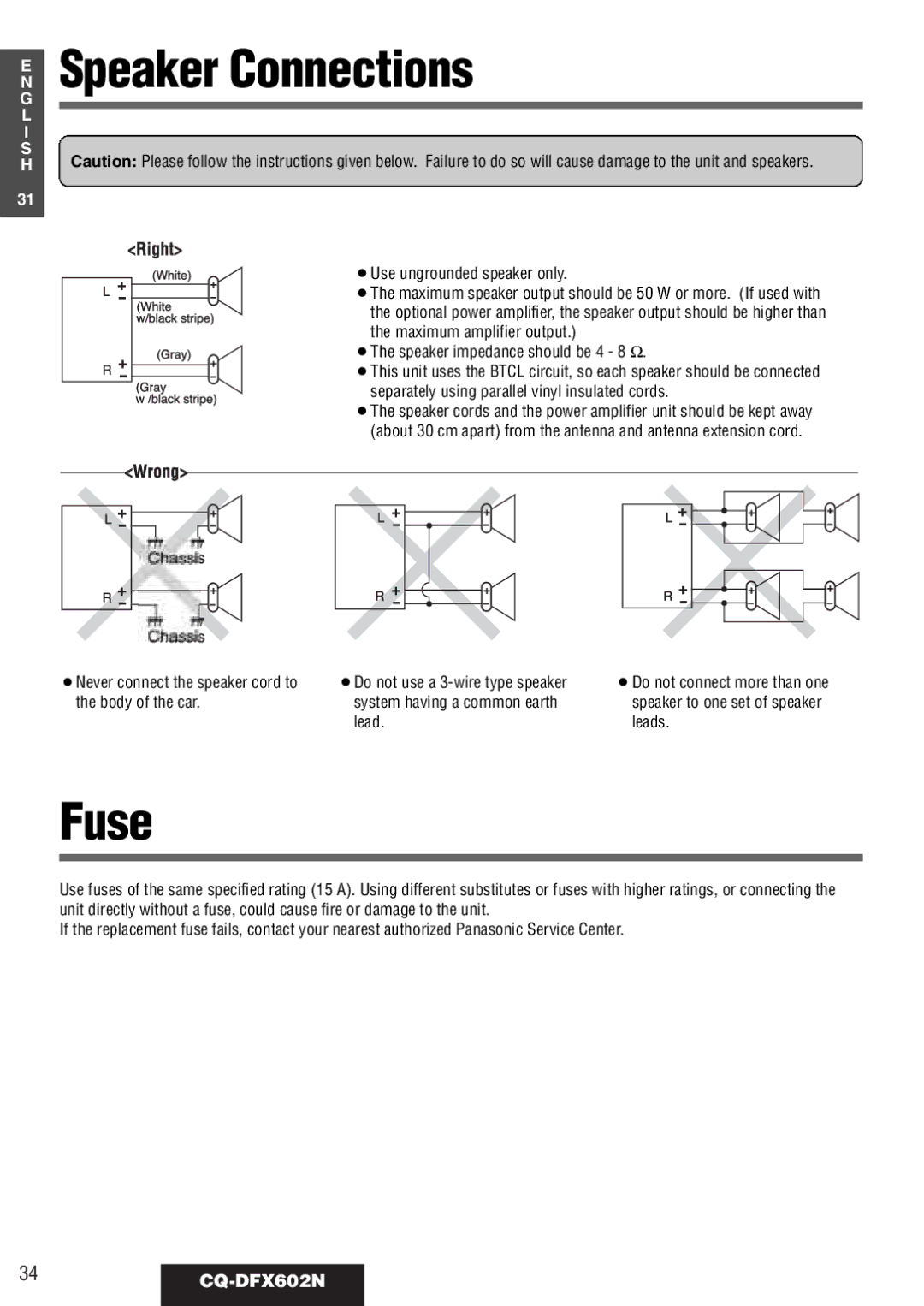
Electrical Connections

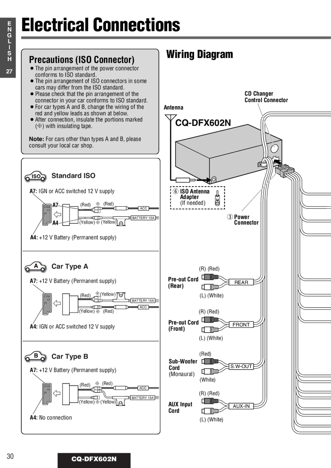
Precautions (ISO Connector)

Wiring Diagram


27¡The pin arrangement of the power connector conforms to ISO standard.

¡The pin arrangement of ISO connectors in some cars may differ from the ISO standard.

¡Please check that the pin arrangement of the connector in your car conforms to ISO standard.

¡For car types A and B, change the wiring of the red and yellow leads as shown at below.

¡After connection, insulate the portions marked (C) with insulating tape.

Note: For cars other than types A and B, please consult your local car shop.

CD Changer

Control Connector

Antenna

CQ-DFX602N

ISO

Standard ISO


A7: IGN or ACC switched 12 V supply

y ISO Antenna


Adapter


A7

(Red)

C (Red)

(If needed)


ACC


BATTERY 15A

e Power


A4

(Yellow) C(Yellow)

Connector

A4: +12 V Battery (Permanent supply)

A

Car Type A

(R) (Red)


A7: +12 V Battery (Permanent supply)

(Red)

C(Yellow)


BATTERY 15A


ACC

(Yellow) C (Red)

A4: IGN or ACC switched 12 V supply

BCar Type B

A7: +12 V Battery (Permanent supply)

(Red) C (Red)

ACC

BATTERY 15A

(Yellow) C(Yellow)

A4: No connection

Pre-out Cord (Rear)

(L) (White)

(R) (Red)

Pre-out Cord (Front)

(L) (White)

(Red)

Sub-Woofer Cord (Monaural)

(White)

(R) (Red)

AUX Input

Cord

(L) (White)

REAR

FRONT

S.W-OUT

AUX-IN

30CQ-DFX602N

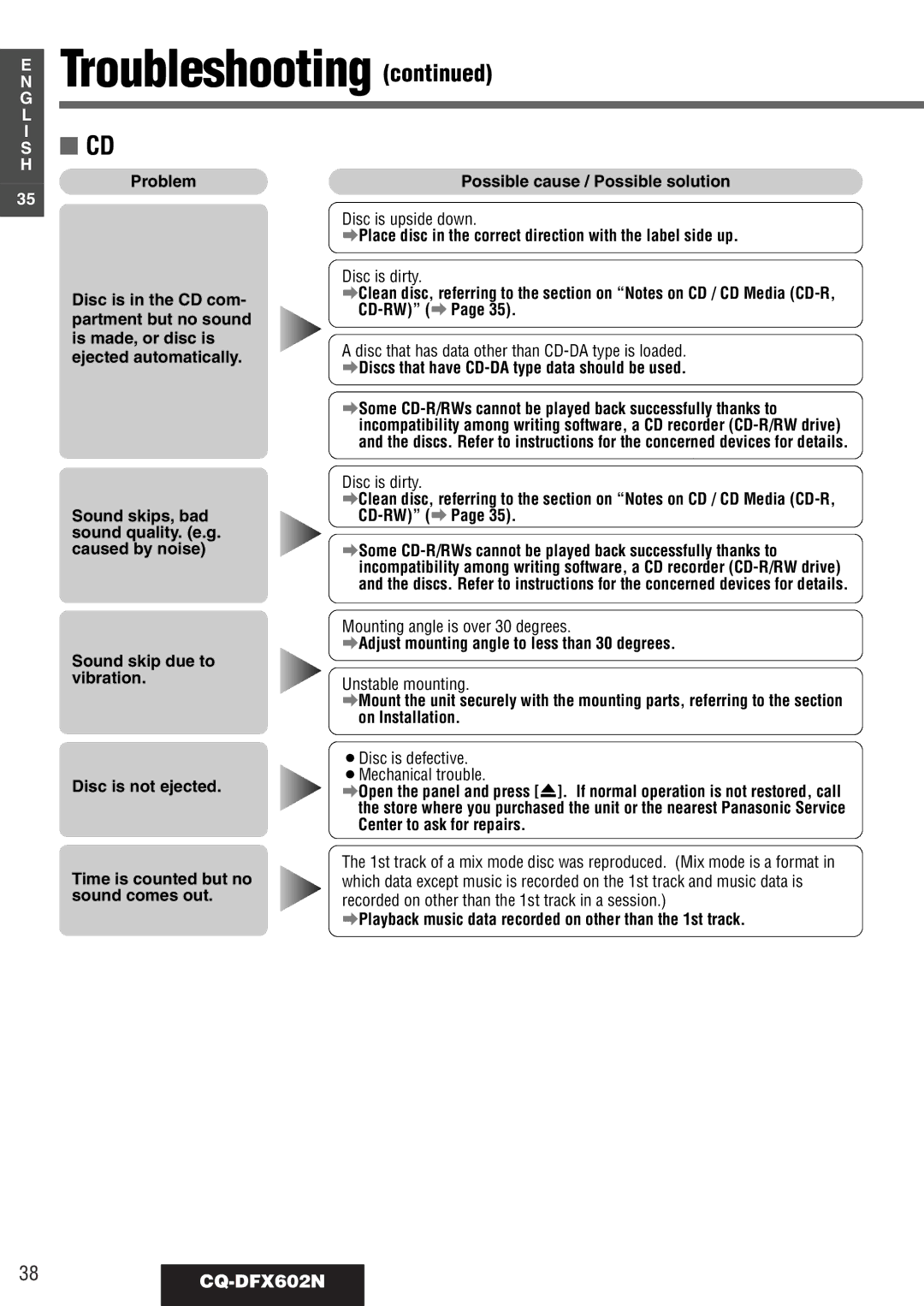
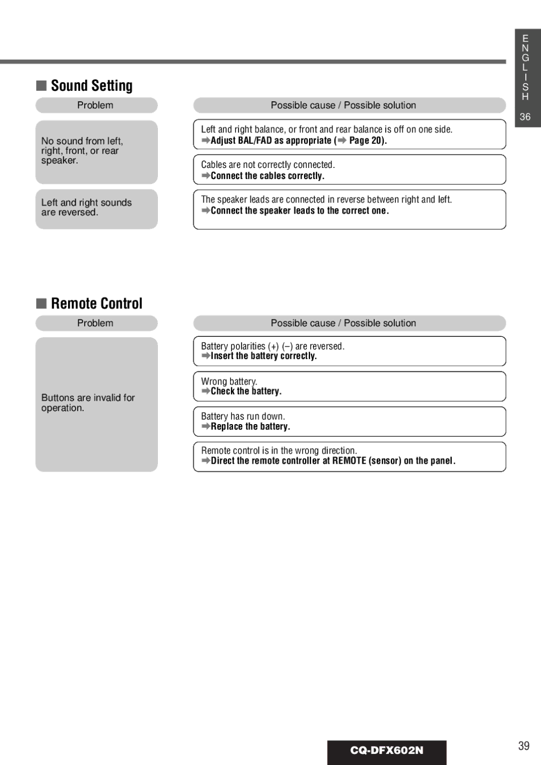
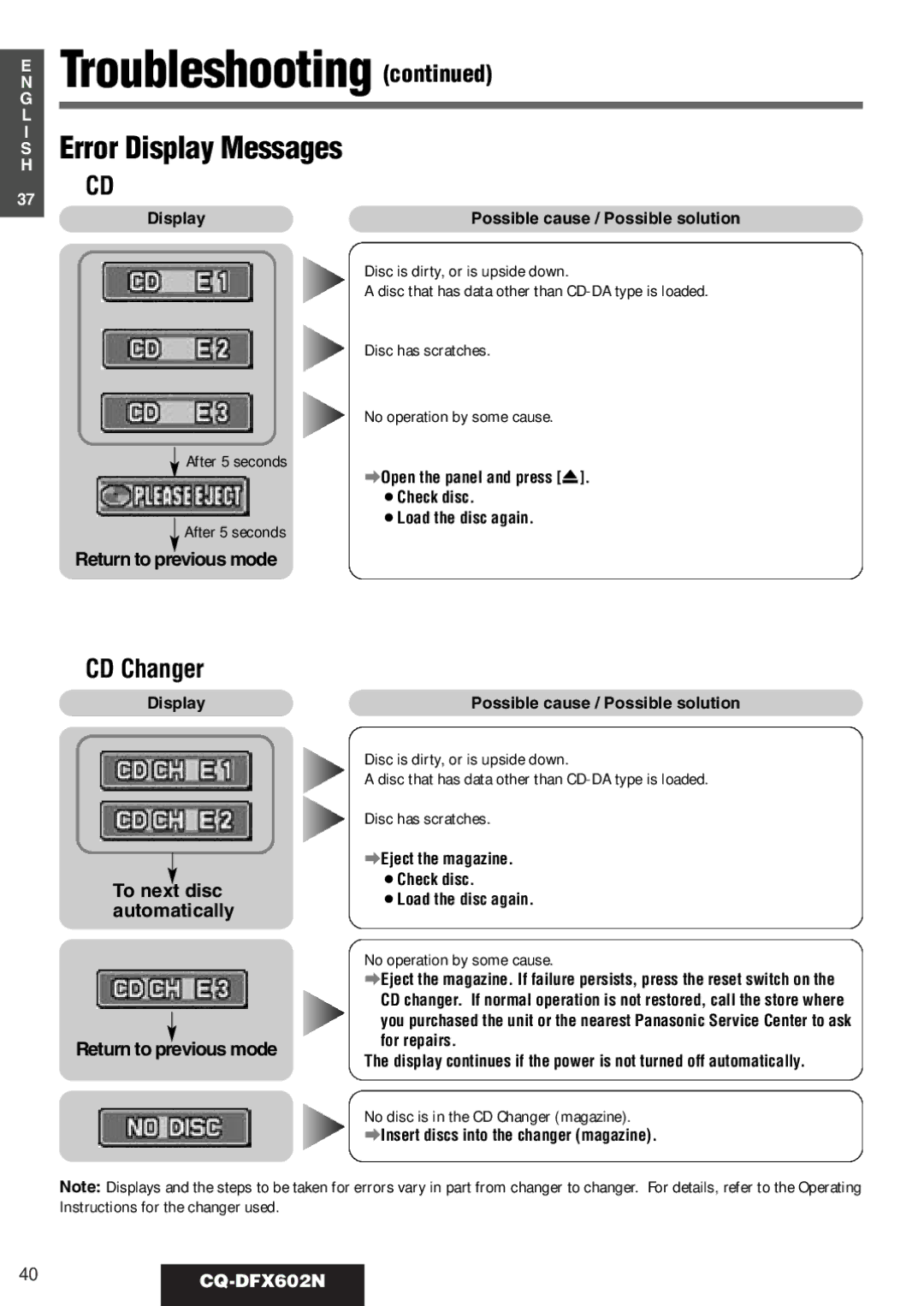
Image 30
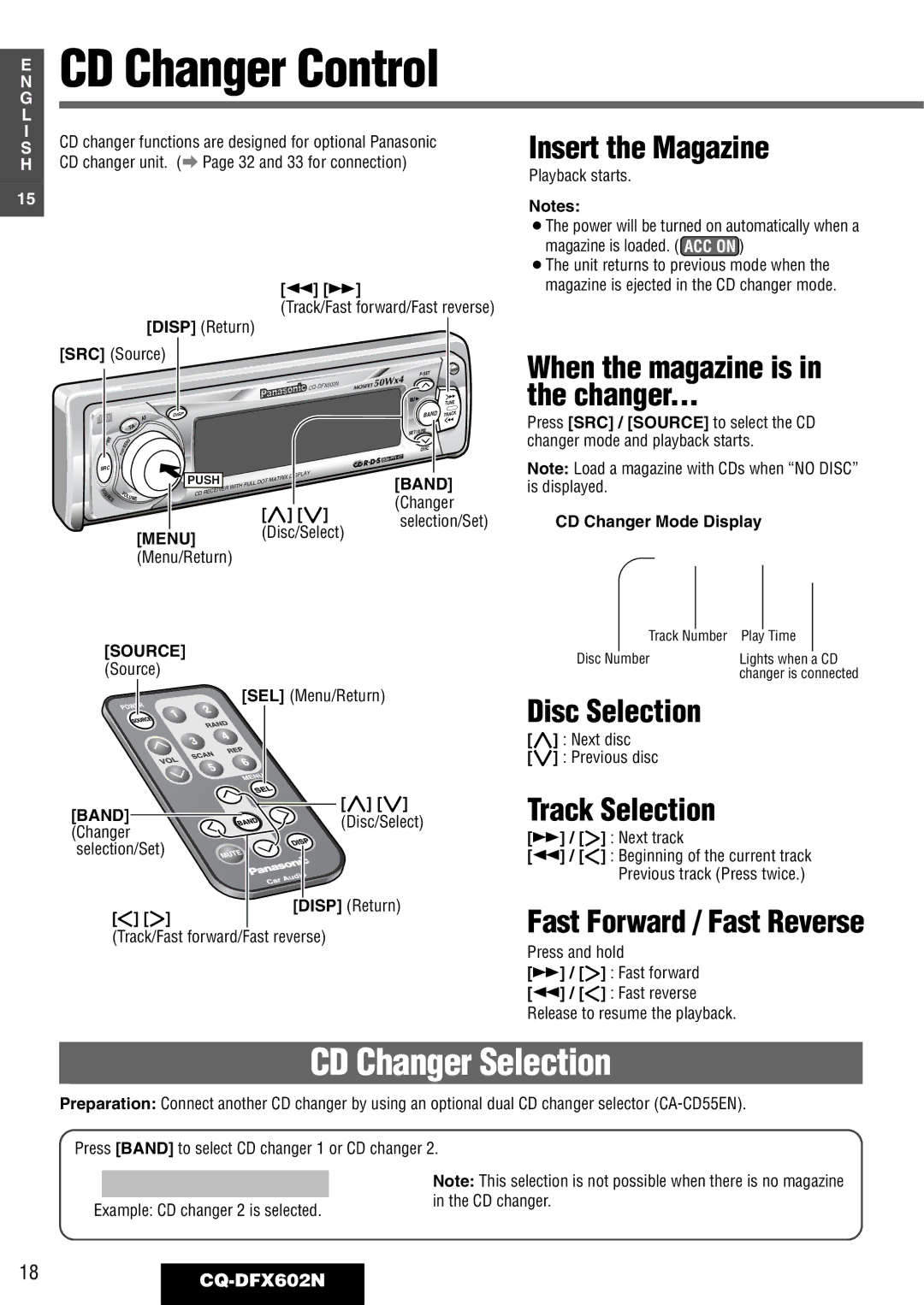
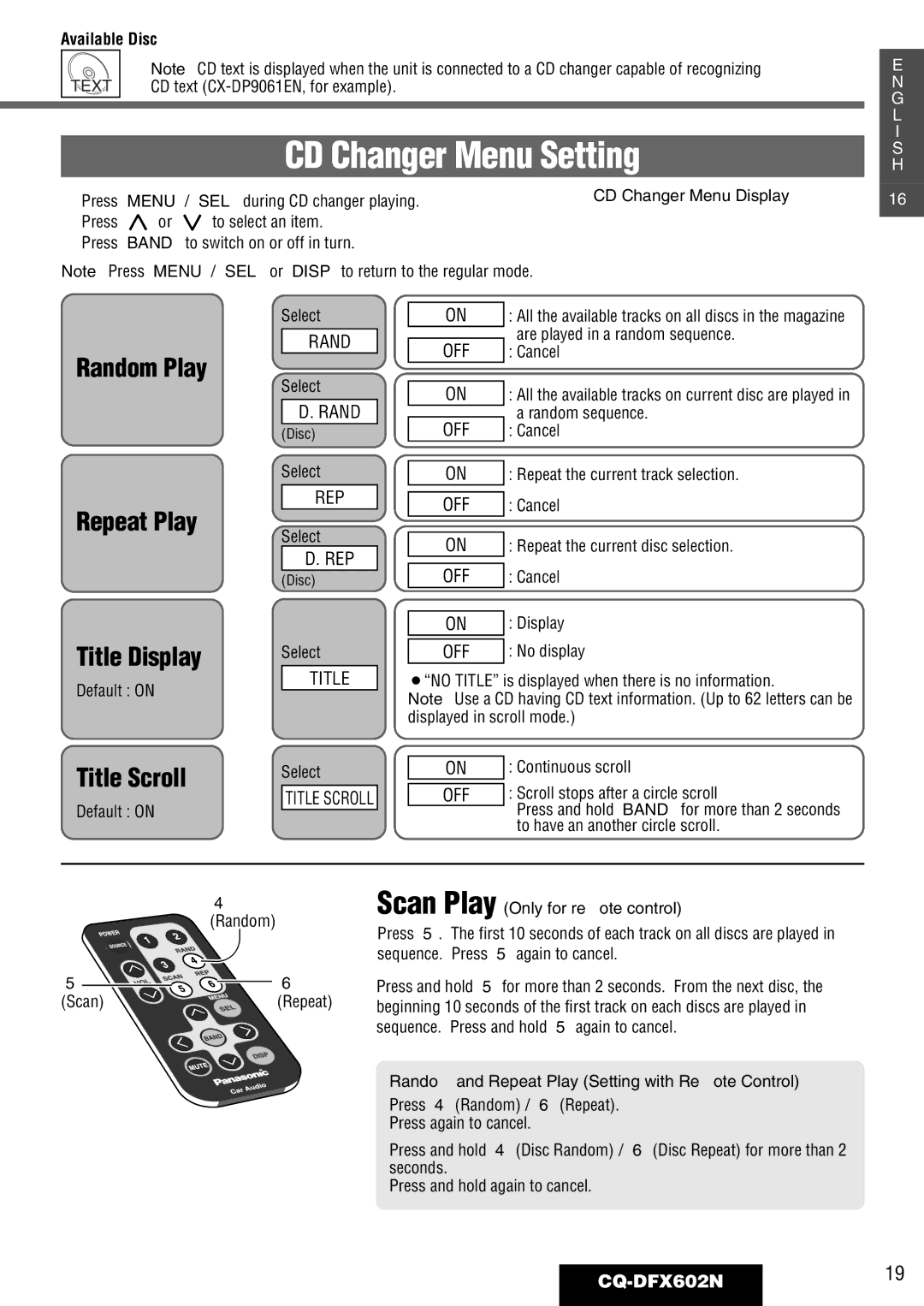
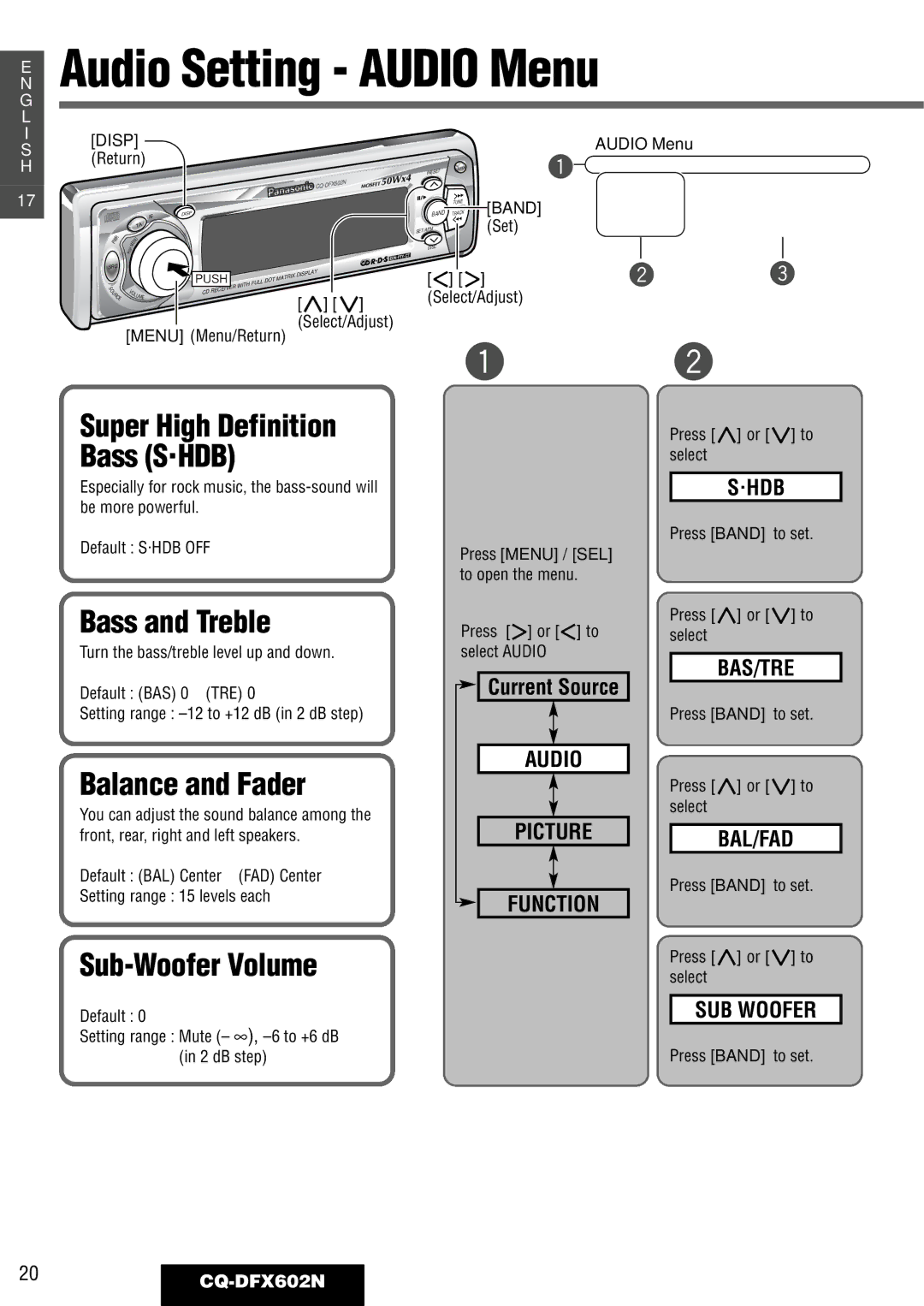
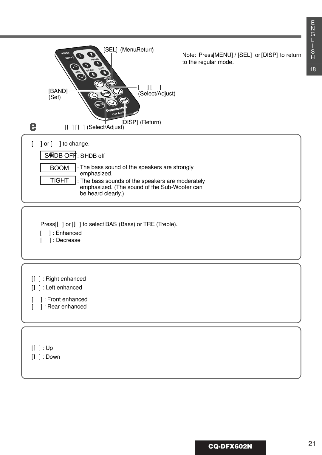
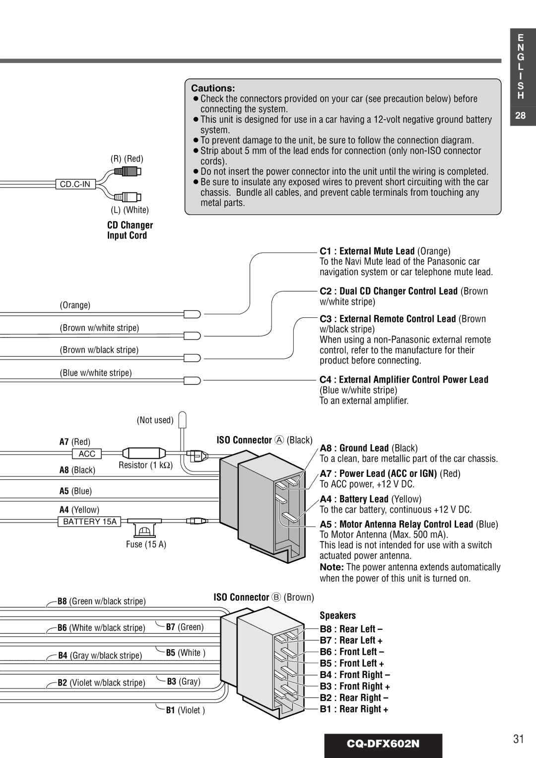
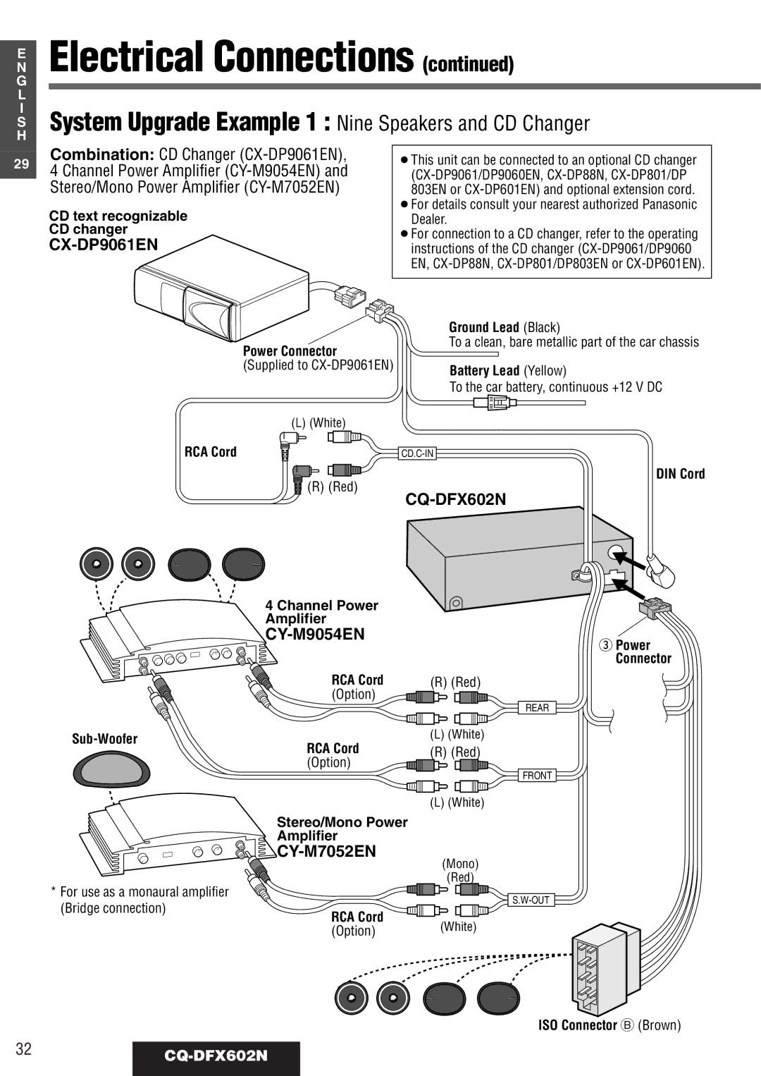
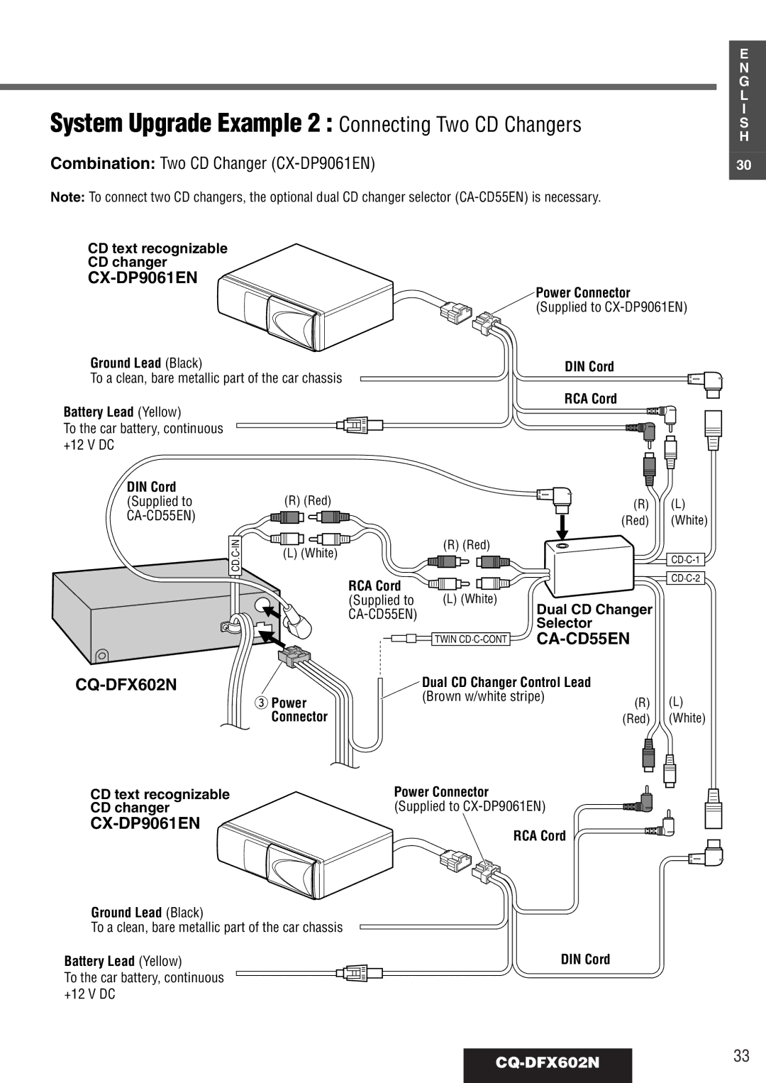
Contents CQ-DFX602N Inhaltsverzeichnis SeiteSicherung PflegePrecautions Remote Control Preparation Battery NotesComponents Power GeneralSource Only for remote control On Press Mute VolumeVolume Clockwise / VOL Up Mute / AttenuationTuning Mono / Local Selection Menu SettingRadio Mode BandPreset Station Station PresetManual Preset MemoryRadio Data System RDS RDS BasicsAlternative Frequency AF AF LevelCQ-DFX602N11 TA Standby Mode TA Volume Set Menu SettingMuting in TA Mode Traffic Announcement TAProgram Type PTY Reception Program Type PTY ModePTY Language Selection Menu Setting PTY SelectionPreset PTY Search PTY Preset CallPTY Preset Change Program Type Preset NumberPTY Preset Default Other RDS functionsCQ-DFX602N15 Insert a Disc CD PlayerOpen the Front Panel Track SelectionCD Menu Setting Random Play Repeat PlayCQ-DFX602N17 Insert the Magazine When the magazine isCD Changer Selection ChangerTitle Scroll CD Changer Menu SettingRandom Play Repeat Play Title Display CQ-DFX602N19Balance and Fader Sub-Woofer VolumeBass and Treble 20CQ-DFX602NSelect/Adjust Disp Return CQ-DFX602N21Contrast Clock AdjustmentDimmer Small Clock DisplayCQ-DFX602N23 Security Function Function Setting Function MenuExternal Mute ACC SelectionCQ-DFX602N25 Security FunctionInstallation Opening InstallationDiagram Q’ty PreparationCQ-DFX602N27 ExampleTabMounting Springs C To Remove the Unit 28CQ-DFX602NPanel Removal Alarm Install Removable Face PlateSecurity Indicator Anti-Theft SystemPrecautions ISO Connector Electrical Connections30CQ-DFX602N CQ-DFX602N31 32CQ-DFX602N System Upgrade Example 2 Connecting Two CD Changers CQ-DFX602N33RCA Cord Ground Lead Black Speaker Connections Fuse34CQ-DFX602N Disc cleaning MaintenanceHow to hold the disc CQ-DFX602N35Common TroubleshootingProduct Service 36CQ-DFX602NRadio CQ-DFX602N37APlace disc in the correct direction with the label side up AAdjust mounting angle to less than 30 degrees38CQ-DFX602N ADiscs that have CD-DA type data should be usedSound Setting Remote ControlCQ-DFX602N39 Error Display Messages CD Changer40CQ-DFX602N General MW Radio SpecificationsCQ-DFX602N41 LW Radio