Heatcraft Refrigeration Products H-IM-CU warranty Diagram City & Tower Water Connections

Page 4

Requirements for Remote and Water Cooled Condensing Units

General Installation

The indoor compressor units are designed to be used with a remote condenser. The water cooled units are similar, except that they have an integral water cooled condenser. Inlet and outlet water connections are to be made in the field. On units having a compressor water jacket, incoming water shall be routed through the jacket prior to entering the condenser. For cleaning purposes, condenser end plates can be removed to give access to the water tubes. Cleaning is accomplished by a simple spiral tool powered by an ordinary electric drill. During installation, allow space for cleaning the condenser. Commercial equipment of this type is intended for installation by qualified refrigeration mechanics.

2.A double riser discharge line may be used as shown in Diagram 2. Line “A” should be sized to carry the oil at minimum load conditions and the line “B” should be sized so that at the full load conditions both lines would have sufficient flow velocity to carry the oil to the condenser.

Water Regulating Valve

Using this control on the water cooled condensing units, the head pressure can be maintained by adjusting the flow of water through the condenser section. This type control is most often located on the water entering side of the condenser and is regulated by the refrigerant condensing pressure.

Typical Arrangements

Diagram 1 illustrates a typical piping arrangement involving a remote condenser located at a higher elevation, as commonly encountered when the condenser is on a roof and the compressor and receiver are on grade level or in a basement equipment room.

In this case, the design of the discharge line is very critical. If properly sized for full load condition, the gas velocity might be too low at reduced loads to carry oil up through the discharge line and condenser coil. Reducing the discharge line size would increase the gas velocity sufficiently at reduced load conditions; however, when operating at full load, the line would be greatly undersized, and thereby creating an excessive refrigerant pressure drop. This condition can be overcome in one of two of the following ways:

1.The discharge line may be properly sized for the desired pressure drop at full load conditions and an oil separator installed at the bottom of the trap in the discharge line from the compressor.

Subcooler

Diagrams 1 and 2 below show typical subcooler piping. Diagram 1 is the preferred connection with receiver as it provides maximum subcooling. Diagram 2 may be used if the receiver is located far from the condenser.

Notes:

1.All oil traps are to be as short in radius as possible. Common practice is to fabricate the trap using three 90 degree ells.

2.Pressure relief valves are recommended at the condenser for protection of the coil.

3.A pressure valve at the high point in the discharge line is recommended to aid in removing non-condensables.

4.The placement of a subcooler should be that it does not interfere with normal airflow of the condenser. Increased static of the unit could cause a decrease in system capacity and fan motor damage.

Diagram 1

Diagram 2


City & Tower Water Connections

In the refrigeration industry “City” and “Tower” are designations of temperature and flow conditions, not applications. The term “City” refers to operating conditions where incoming water is 75˚F, and condensing temperature is 105˚F. “Tower” refers to a higher temperature relationship which is normally 85˚F, incoming water and 105˚F condensing temperature.

Water circuits in some condenser models provide a center, or Tower, outlet connection to allow divided inlet water flow. This extra water port reduces water velocity, water pressure drop, and condenser wear in applications such as cooling towers where higher inlet temperatures and water flows occur.

Water Connections for City

For City water (open system) high pressure applications, the Tower connections is plugged.

Water Connections for Tower

For Tower usage and low pressure applications, both normal water connections will be used as inlets and the tower connection as an outlet.

Figure 2. Water Connections


Image 4
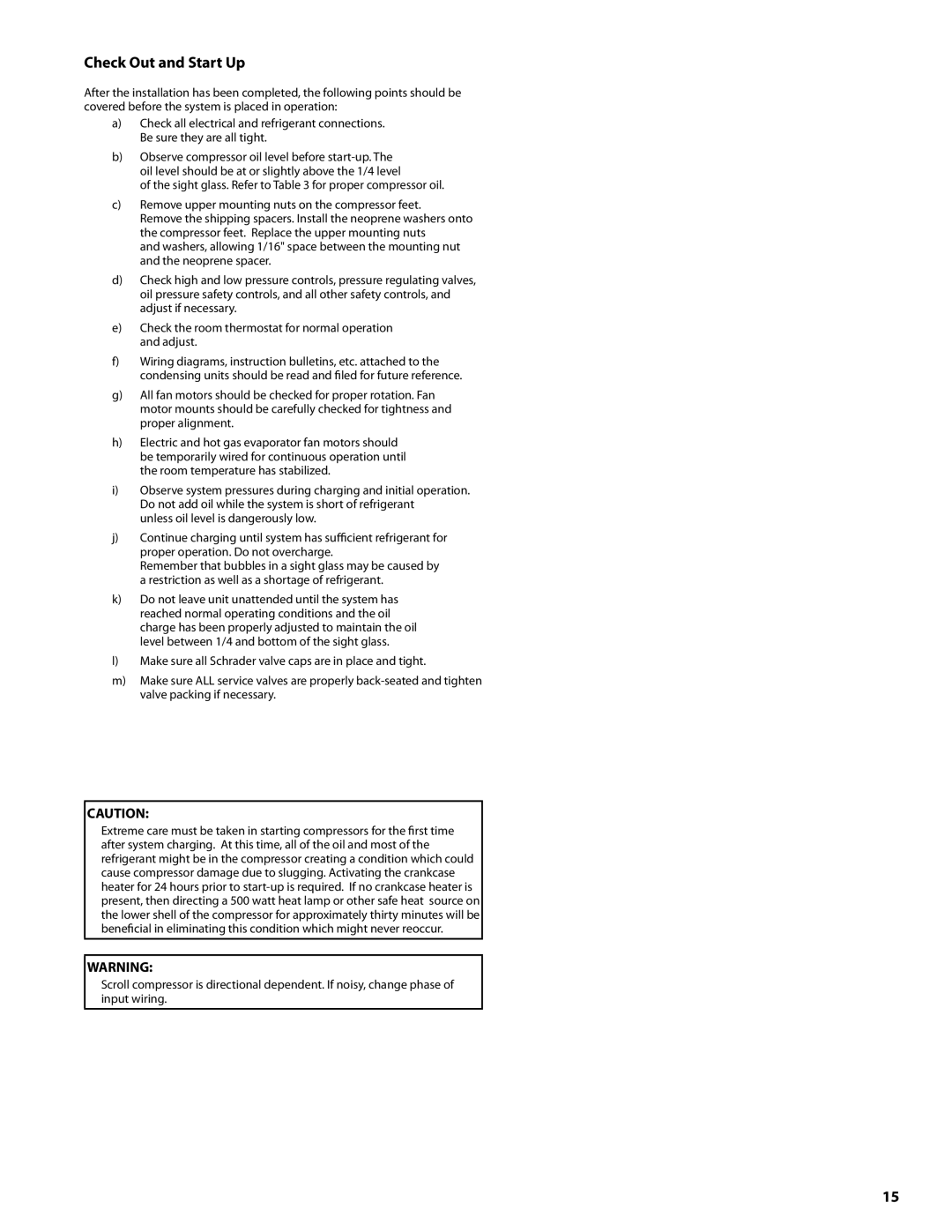
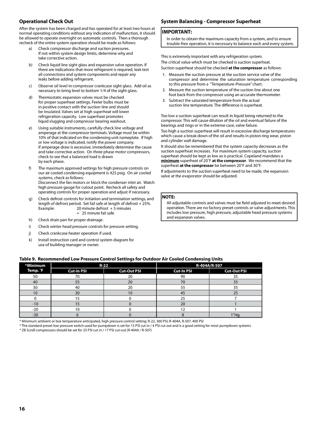
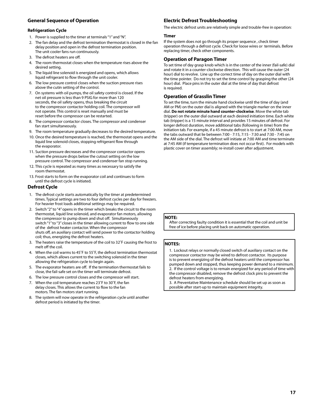
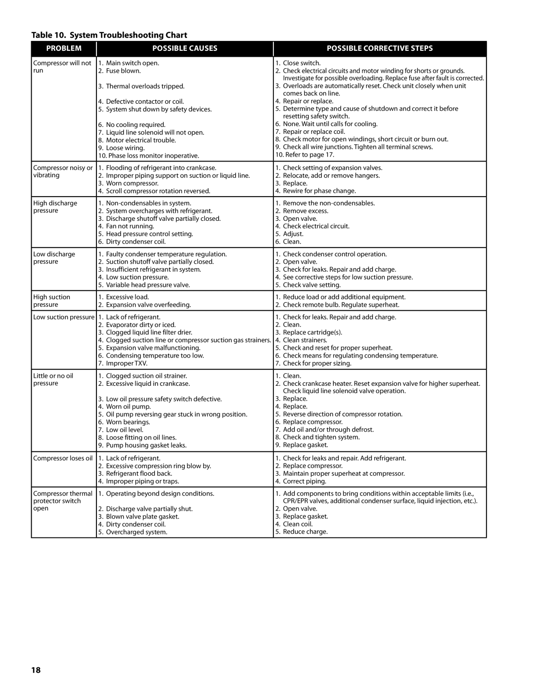
Contents Units Warranty Statement General Safety InformationSome units are pressurized with dry air or inert gas Decorative Fences Diagram City & Tower Water Connections Requirements for Remote and Water Cooled Condensing UnitsCondensing Unit Rigging and Mounting Ambient Fan Cycle Thermostat Settings Head Pressure ControlRefrigeration Oils Oil TypesPolyol Ester Lubricants Mineral OilsPhase Loss Monitor Recommended Refrigerant Piping PracticesRefrigerant Pipe Support Suction LinesHot Gas Defrost Systems Liquid LinesHot gas line sizes for R-22, R404A and R507 Unit Cooler Piping Line SizingRecommended Remote Condenser Line Sizes Equivalent Feet of Pipe Due to Valve and Fitting FrictionCopper Tube, O.D., Type L Globe Valve Open Recommended Line Sizes for R-22 000Recommended Line Sizes for R-404A and R507 Evacuation and Leak Detection Field WiringRefrigerant Charging Instructions Check Out and Start Up System Balancing Compressor Superheat Operational Check OutExample Electric Defrost Troubleshooting Operation of Paragon TimerOperation of Grasslin Timer General Sequence of OperationClean strainers System Troubleshooting ChartCheck liquid line solenoid valve operation Unit Coolers Preventive MaintenanceAir-Cooled Condensing Units Page Page Page Page Replacement Parts by

H-IM-CU specifications

Heatcraft Refrigeration Products has long been recognized as a leader in the refrigeration industry, and their H-IM-CU model is a prime example of innovative design and cutting-edge technology. The H-IM-CU is engineered to deliver exceptional performance and efficiency, catering to various commercial refrigeration needs.

One of the standout features of the H-IM-CU is its robust construction. The unit is designed with high-quality materials that ensure durability and long-lasting performance in demanding environments. This construction not only protects against wear and tear but also supports the reliable operation essential for business continuity.

The H-IM-CU incorporates advanced cooling technologies that enhance its efficiency. Equipped with a high-efficiency compressor, this model optimizes energy consumption, reducing operational costs while still maintaining optimal refrigerant temperatures. This energy-efficient design is particularly beneficial for businesses looking to minimize their carbon footprint and achieve sustainability goals.

An important characteristic of the H-IM-CU is its user-friendly control system. The intuitive interface allows operators to easily adjust and monitor temperature settings, ensuring that products are stored in favorable conditions. This user-centric design simplifies the management of refrigeration units, making it easier for staff to perform routine tasks.

Additionally, the H-IM-CU features a whisper-quiet operation, which is an advantage for businesses that prioritize a pleasant customer experience. This is achieved through effective sound-dampening technologies and smart engineering that minimize noise without compromising cooling performance.

Another significant highlight is the versatility of the H-IM-CU. It is suitable for a wide range of applications, from convenience stores to restaurants and supermarkets. This adaptability makes it a preferred choice for businesses seeking a reliable refrigeration solution that can cater to their specific needs.

Furthermore, the model boasts enhanced airflow technology that ensures even temperature distribution throughout the unit. This promotes efficient cooling and eliminates hotspots, keeping products at the desired temperature consistently.

Overall, the Heatcraft Refrigeration Products H-IM-CU stands out as a leading choice in commercial refrigeration. With its combination of durability, energy efficiency, user-friendly controls, quiet operation, and versatility, it meets the high standards of modern businesses looking for reliable cooling solutions. Investing in the H-IM-CU not only enhances product longevity but also aids in operational efficiency, making it a wise choice for any commercial refrigeration setup.