Distribution entities
MDSD is described as both a separation of concerns, where designers can
address each set of stakeholder concerns independently, as well as an integration of concerns, where there is enforcement of integration by requiring
the use of a common set of design elements across multiple sets of concerns.
One of the concerns is the logical aspects of the system that have been described already. Another is the distribution aspects of the system. (There can
be many more, such as process, security, and so forth.) The entities used to model this viewpoint are called localities. The distribution viewpoint describes
how the functionality of the system is distributed.
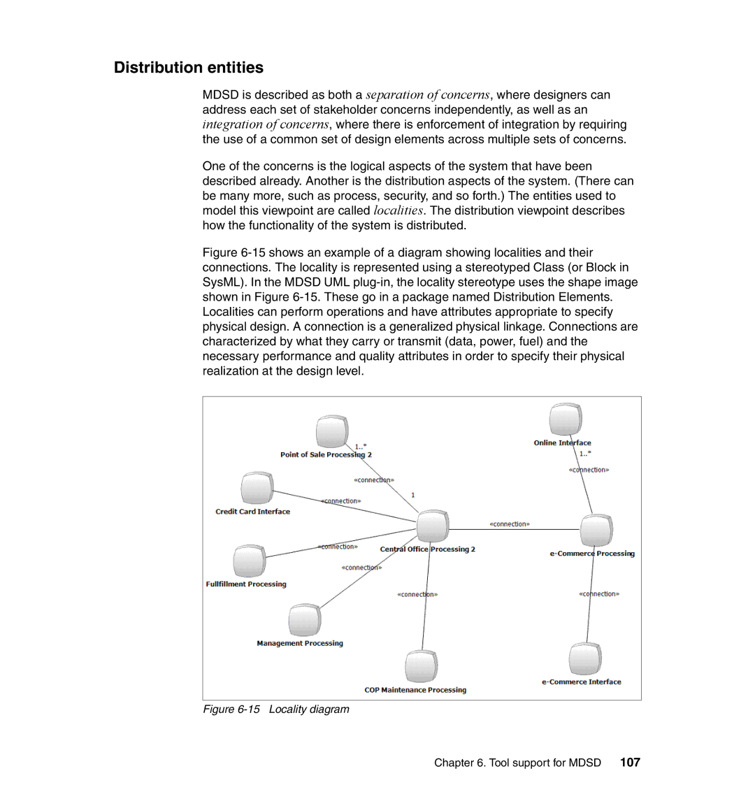
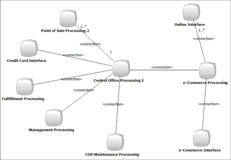
Figure 6-15 shows an example of a diagram showing localities and their connections. The locality is represented using a stereotyped Class (or Block in SysML). In the MDSD UML plug-in, the locality stereotype uses the shape image shown in Figure 6-15. These go in a package named Distribution Elements. Localities can perform operations and have attributes appropriate to specify physical design. A connection is a generalized physical linkage. Connections are characterized by what they carry or transmit (data, power, fuel) and the necessary performance and quality attributes in order to specify their physical realization at the design level.
Figure 6-15 Locality diagram
Chapter 6. Tool support for MDSD 107