To determine an entity’s operations on a sequence diagram, note the arrows pointing into the lifeline and originating from another lifeline only. When working with paper
To put it simply, if the entity is at some point requested, by any actor, to unlock, then it is required that the entity have an operation called unlock. It is as simple
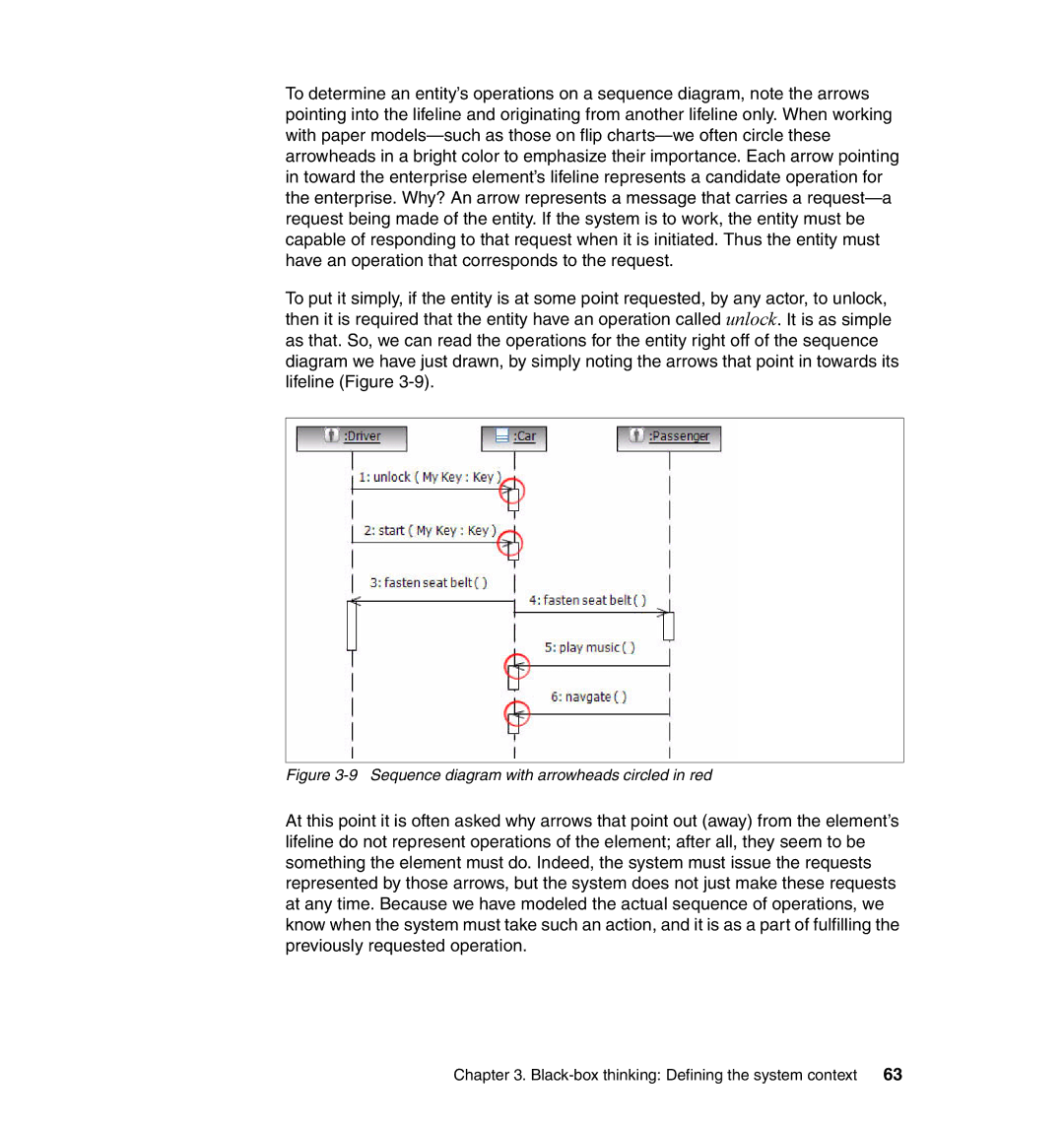
as that. So, we can read the operations for the entity right off of the sequence diagram we have just drawn, by simply noting the arrows that point in towards its lifeline (Figure
Figure 3-9 Sequence diagram with arrowheads circled in red
At this point it is often asked why arrows that point out (away) from the element’s lifeline do not represent operations of the element; after all, they seem to be something the element must do. Indeed, the system must issue the requests represented by those arrows, but the system does not just make these requests at any time. Because we have modeled the actual sequence of operations, we know when the system must take such an action, and it is as a part of fulfilling the previously requested operation.
Chapter 3. | 63 |