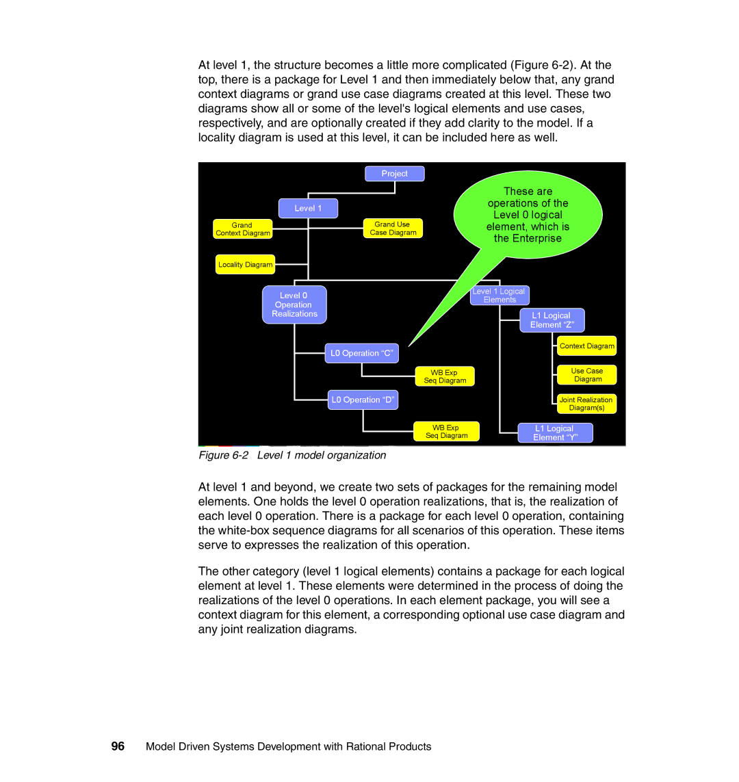
At level 1, the structure becomes a little more complicated (Figure
| Project |
| Level 1 |
Grand | Grand Use |
Context Diagram | Case Diagram |
Locality Diagram |
|
These are
operations of the
Level 0 logical
element, which is
the Enterprise
Level 0 | Level 1 Logical | |
Elements | ||
Operation | ||
| ||
Realizations | L1 Logical | |
| Element “Z” | |
L0 Operation “C” | Context Diagram | |
| ||
WB Exp | Use Case | |
Seq Diagram | Diagram | |
L0 Operation “D” | Joint Realization | |
| Diagram(s) | |
WB Exp | L1 Logical | |
Seq Diagram | Element “Y” |
Figure 6-2 Level 1 model organization
At level 1 and beyond, we create two sets of packages for the remaining model elements. One holds the level 0 operation realizations, that is, the realization of each level 0 operation. There is a package for each level 0 operation, containing the
The other category (level 1 logical elements) contains a package for each logical element at level 1. These elements were determined in the process of doing the realizations of the level 0 operations. In each element package, you will see a context diagram for this element, a corresponding optional use case diagram and any joint realization diagrams.
