more is learned over the course of the system development effort. Eventually the entire model comes together.
This is also true when deciding whether to reason about distribution issues first with sequence diagrams, or with joint realization tables. In all likelihood, we should perform both activities in
Joint realization tables
In MDSD, we distinguish between functional requirements and nonfunctional requirements (NFRs). Functional requirements describe the system behavior as well as the collaboration among system components to accomplish the system behavior. NFRs pertain to how a system performs its functions and include concerns such as quality, quantity, and timeliness.
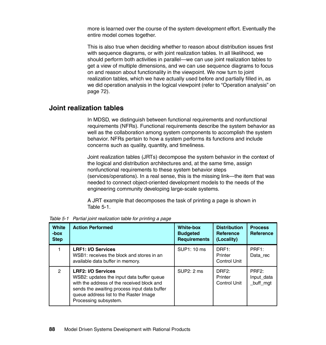
Joint realization tables (JRTs) decompose the system behavior in the context of the logical and distribution architectures and, at the same time, assign nonfunctional requirements to these system behavior steps (services/operations). In a real sense, this is the missing
A JRT example that decomposes the task of printing a page is shown in
Table
Table
White | Action Performed | Distribution | Process | |
| Budgeted | Reference | Reference | |
Step |
| Requirements | (Locality) |
|
|
|
|
|
|
1 | LRF1: I/O Services | SUP1: 10 ms | DRF1: | PRF1: |
| WSB1: receives the block and stores in an |
| Printer | Data_rec |
| available data buffer in memory. |
| Control Unit |
|
|
|
|
|
|
2 | LRF2: I/O Services | SUP2: 2 ms | DRF2: | PRF2: |
| WSB2: updates the input data buffer queue |
| Printer | Input_data |
| with the address of the received block and |
| Control Unit | _buff_mgt |
| sends the awaiting process input data buffer |
|
|
|
| queue address list to the Raster Image |
|
|
|
| Processing subsystem. |
|
|
|
|
|
|
|
|