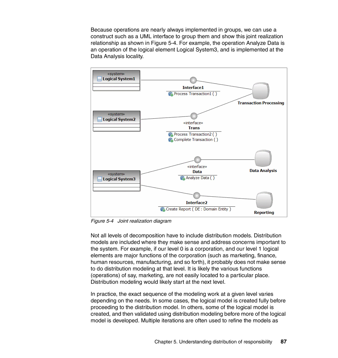
Because operations are nearly always implemented in groups, we can use a construct such as a UML interface to group them and show this joint realization relationship as shown in Figure
Figure 5-4 Joint realization diagram
Not all levels of decomposition have to include distribution models. Distribution models are included where they make sense and address concerns important to the system. For example, if our level 0 is a corporation, and our level 1 logical elements are major functions of the corporation (such as marketing, finance, human resources, manufacturing, and so forth), it probably does not make sense to do distribution modeling at that level. It is likely the various functions (operations) of say, marketing, are not easily located to a particular place. Distribution modeling would likely start at the next level.
In practice, the exact sequence of the modeling work at a given level varies depending on the needs. In some cases, the logical model is created fully before proceeding to the distribution model. In others, some of the logical model is created, and then validated using distribution modeling before more of the logical model is developed. Multiple iterations are often used to refine the models as
Chapter 5. Understanding distribution of responsibility | 87 |