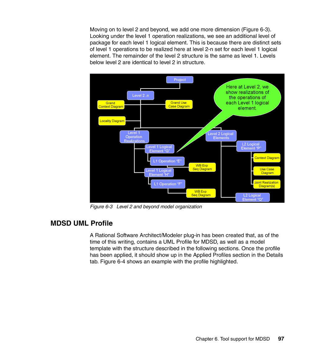
Moving on to level 2 and beyond, we add one more dimension (Figure
| Project |
| Level 2..n |
Grand | Grand Use |
Context Diagram | Case Diagram |
Locality Diagram |
|
Here at Level 2, we show realizations of the operations of each Level 1 logical element.
Level 1 | Level 2 Logical |
|
Operation | Elements |
|
Realizations |
| L2 Logical |
Level 1 Logical |
| |
| Element “P” | |
Element “G” |
| |
|
| |
L1 Operation “E” |
| Context Diagram |
WB Exp |
| |
|
| |
Level 1 Logical | Seq Diagram | Use Case |
Element “H” |
| Diagram |
|
| |
L1 Operation “F” |
| Joint Realization |
| Diagram(s) | |
|
| |
| WB Exp | L2 Logical |
| Seq Diagram | |
|
| Element “Q” |
Figure 6-3 Level 2 and beyond model organization
MDSD UML Profile
A Rational Software Architect/Modeler
Chapter 6. Tool support for MDSD 97