Installing the New Water Heater (cont'd)
Venting (cont'd)
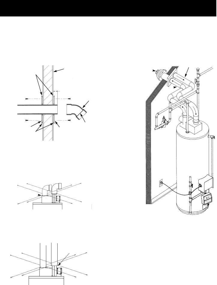
INSTALLATION SHOWING USE OF PVC, ABS OR CPVC PIPE FOR INLET AND OUTLET VENT PIPING:
Inlet piping through any type wall.
SILICONE | EXTERIOR WALL |
SEALER |
|
11⁄2″ MIN. EXTENSION
THROUGH
EXTERIOR WALL
VENT CAP MUST
BE POSITIONED
DOWNWARD
SCREW | SCREW |
SCREW | SCREW | SCREEN AT |
FLUE MOUNTING ADAPTOR | FLUE MOUNTING | OUTLET |
|
| |
SILICONE SEALER | ADAPTOR |
|
|
|
CONNECTING VENT TO BLOWER
1.If making an immediate horizontal run of vent off the blower, one 3″ PVC inlet and one 3″ PVC (ABS for 75 Gal. Models and 50 Gal. 65,000 Btu/Hr Models) outlet Schedule 40 street elbows are required. Place the elbow in the required direction on the blower and using 3 sheet metal screws, attach the elbow.
CAULK
JOINTS ![]()
2.If there is to be a vertical run of vent from the blower, the 3″ PVC inlet and the 3″ PVC (ABS for 75 Gal. Models and 50 Gal. 65,000 Btu/Hr Models) outlet pipes must be attached to the blower and venting hood, using 6 sheet metal screws.
CAULK
JOINTS
INSTALLATION SHOWING USE OF (OPTIONAL) DELUXE HORIZONTAL VENT KIT:
Typical installation.
AIR INTAKE
VENT TO ![]() PIPE
PIPE
OUTDOORS
INTAKE FOR ![]()
COMBUSTION AIR
FLUE PRODUCTS![]()
DISCHARGE PIPE
If this concentric flue, through the wall type of venting sys- tem is preferred, the vent kit can be ordered from the Service Parts Dept. under kit #9002749. See also pages 34 to 37. Installation instructions are provided with the kit.
VENTING THROUGH A ROOF
Two 3″ inlet and outlet PVC Schedule 40 45° vent caps are supplied.
A 5’ section of 3″ ABS Schedule 40 outlet vent pipe (75 Gal. Models and 50 Gal. 65,000 Btu/Hr Models only) is sup- plied. (More may be required and must be supplied locally).
1.The water heater requires its own (separate) venting system.
17