Bosch Appliances GWH 2400 ES NG, GWH 2400 ES LP manual Combustion air requirements, Twin pipe

Page 15

Installation instructions

signage installed in accordance with the provisions of 248 CMR 5.08(2)(a)1 through 4.

(b)EXEMPTIONS: The following equipment is exempt from 248 CMR 5.08(2)(a)1 through 4:

1.The equipment listed in Chapter 10 entitled "Equipment Not Required To Be Vented" in the most current edition of NFPA 54 as adopted by the Board; and

2.Product approved side wall horizontally vented gas fueled equipment installed in a room or structure separate from the dwelling, building or structure used in whole or in part for residential purposes.

(c)MANUFACTURERS REQUIREMENTS - GAS EQUIPMENT VENTING SYSTEM REQUIRED. When the manufacturer of Product Approved side wall horizontally mounted gas equipment provides a venting system design or venting system components with the equipment, the instructions provided by the manufacturer for the installation of the equipment and the venting shall include:

1.Detailed instructions for the installation of the venting system or the venting system components: and

2.A complete parts list for the venting system design or venting system.

(d)MANUFACTURER REQUIREMENTS - GAS EQUIPMENT VENTING SYSTEM NOT PROVIDED. When the manufacturer of a product approved side wall horizontally vented gas fueled equipment does not provide the parts for the venting of flue gases, but identifies "special venting systems," the following requirements shall be satisfied by the manufacturer:

1.The referenced "special venting system" instructions shall be included with the appliance or equipment installation instructions; and

2.The "special venting systems" shall be product approved by the Board, and the instructions for that system shall include a parts list and detailed installation instructions.

(e)A copy of all installation instructions for all products approved side wall horizontally vented gas fueled equipment, all venting instructions, all parts lists for venting instructions, and/or all venting design instructions shall remain with the appliance or equipment at the completion of the installation.

3.4Combustion air requirements

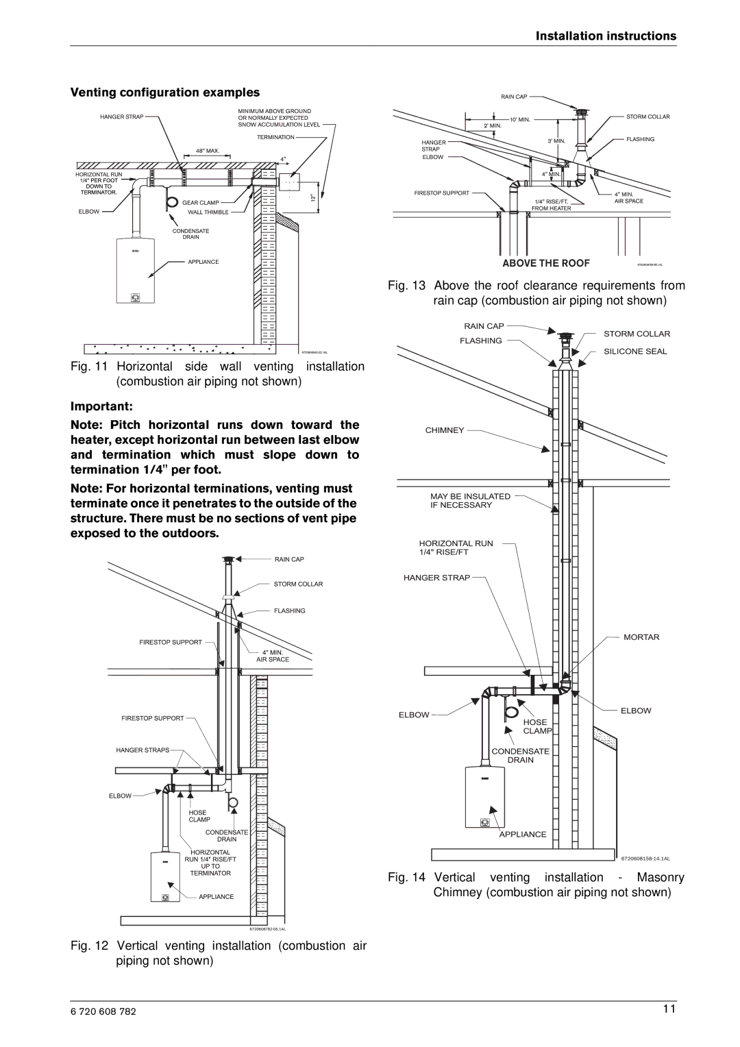
Warning: In areas where outside temperatures routinely come close to freezing, sealed combustion operation is required. Use a concentric termination or separate terminations for combustion and vent, which must be installed on the same wall or roof surface, however never facing the direction of prevailing winds. Failure to do so may result in heat exchanger freezing up and bursting. This failure is not covered under the manufacturer's warranty.

Warning: When installed in an environment where corrosive chemicals or dirty air are present the twin pipe system is required.

Twin pipe

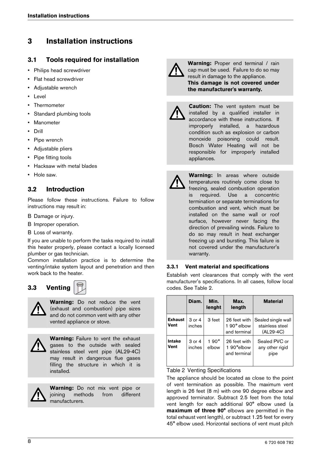
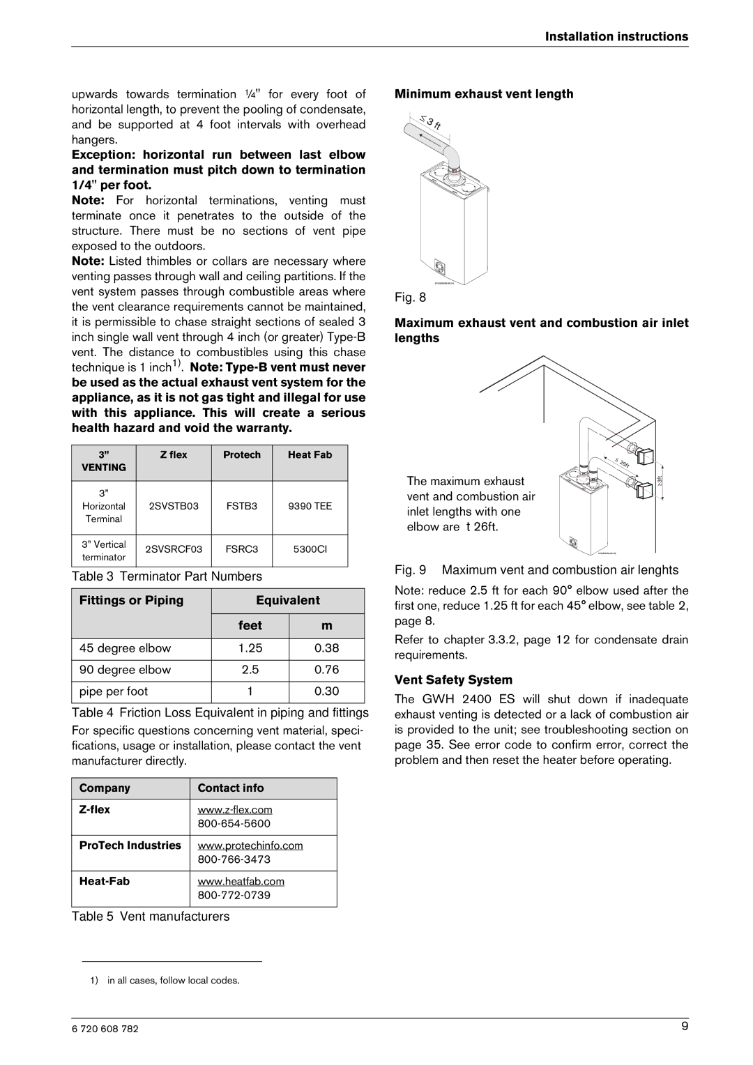
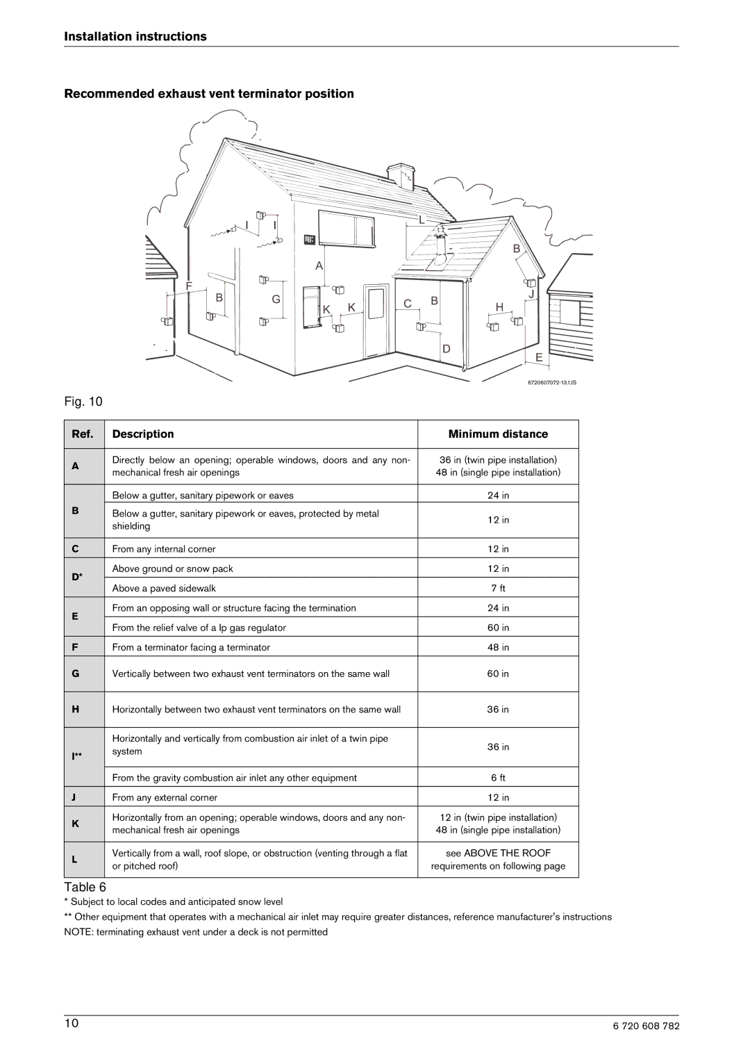
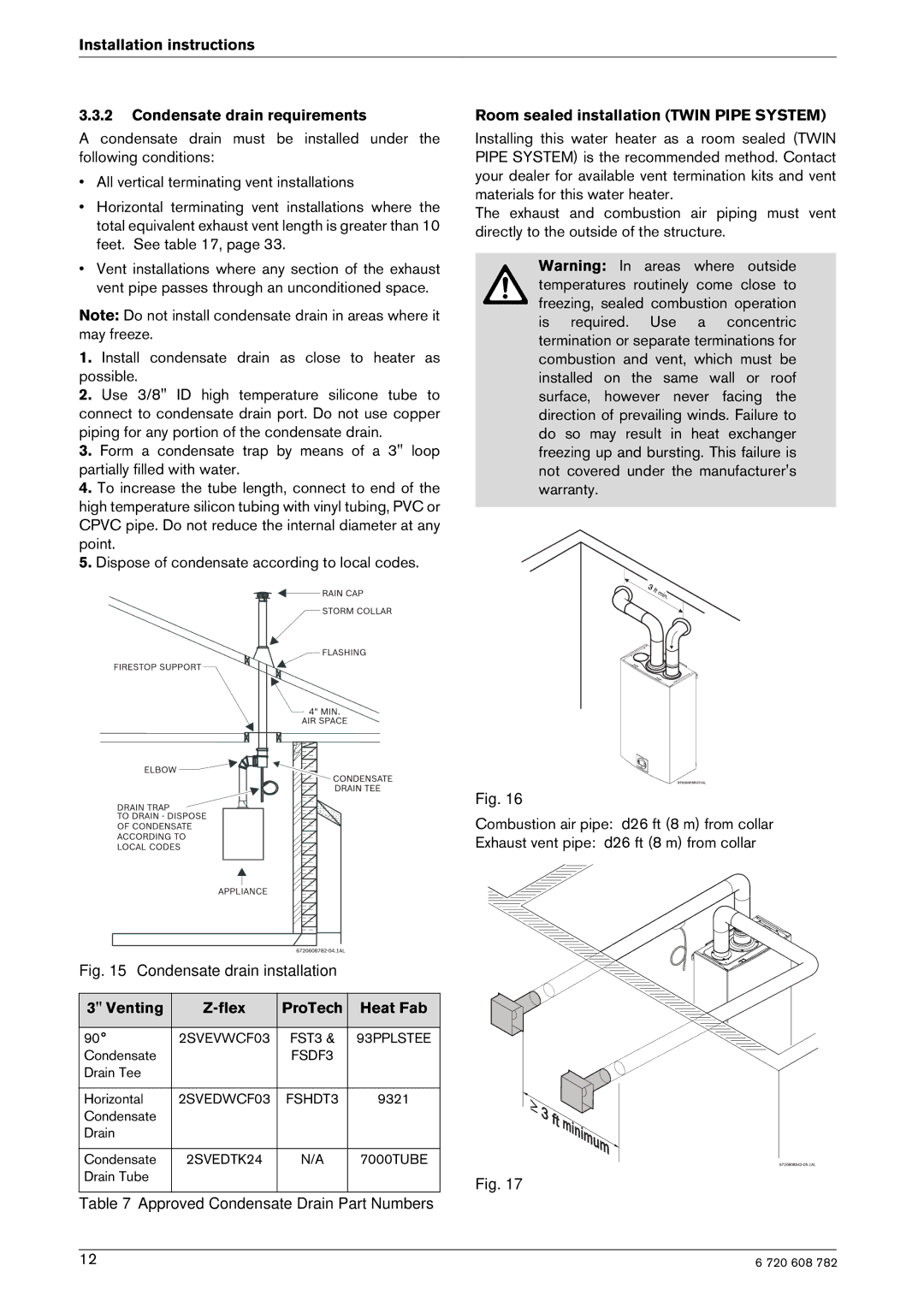
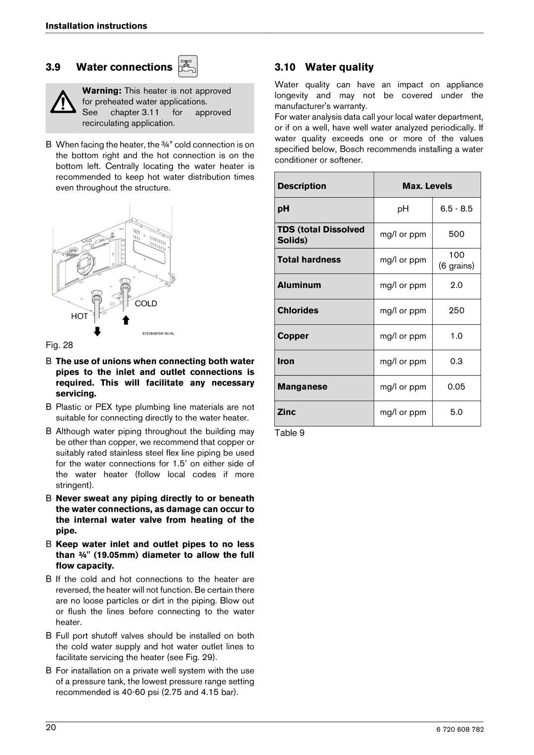
The GWH 2400 ES is designed as a sealed combustion appliance. It is recommended that the combustion air be provided by a dedicated 3” or 4” pipe from the outside. The combustion air pipe may be PVC or any other rigid sealed 3” or 4" pipe. The combustion air piping must pitch down 1/4 inch per foot towards termination to prevent rain water from entering the appliance. The combustion air inlet, whether terminating vertically or horizontally, must be located in such a manner as to provide a minimum 3 foot clearance from the exhaust vent terminator. See Fig. 10 Letter I, page 10.

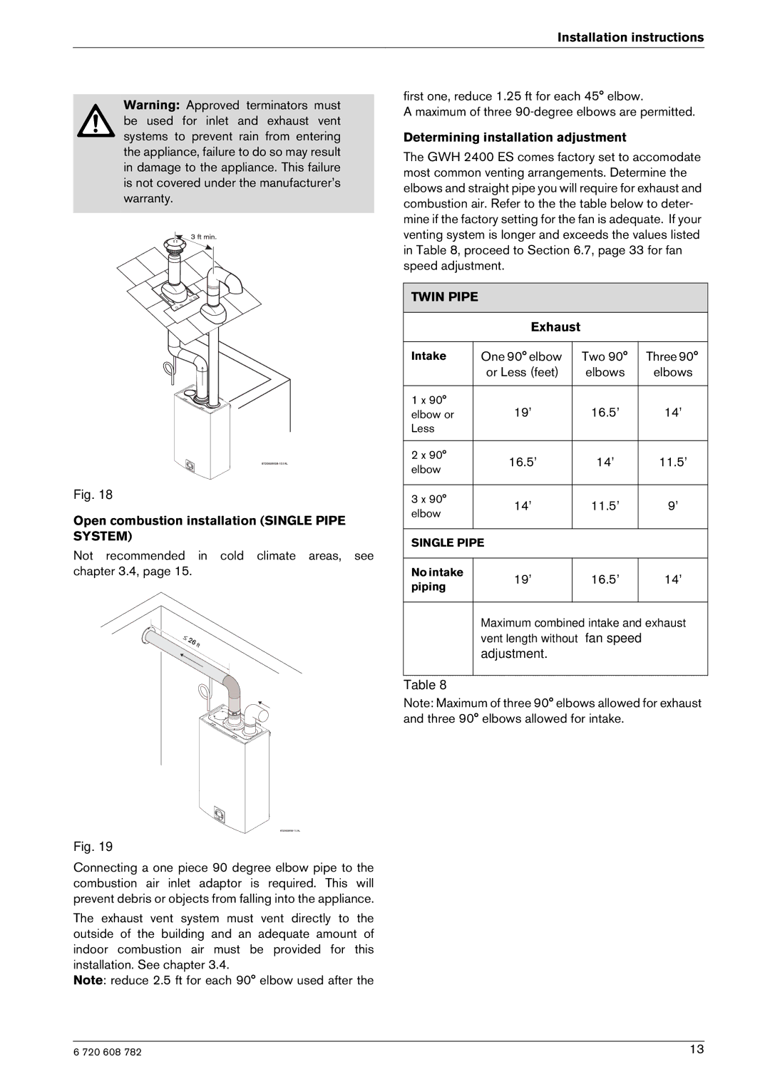
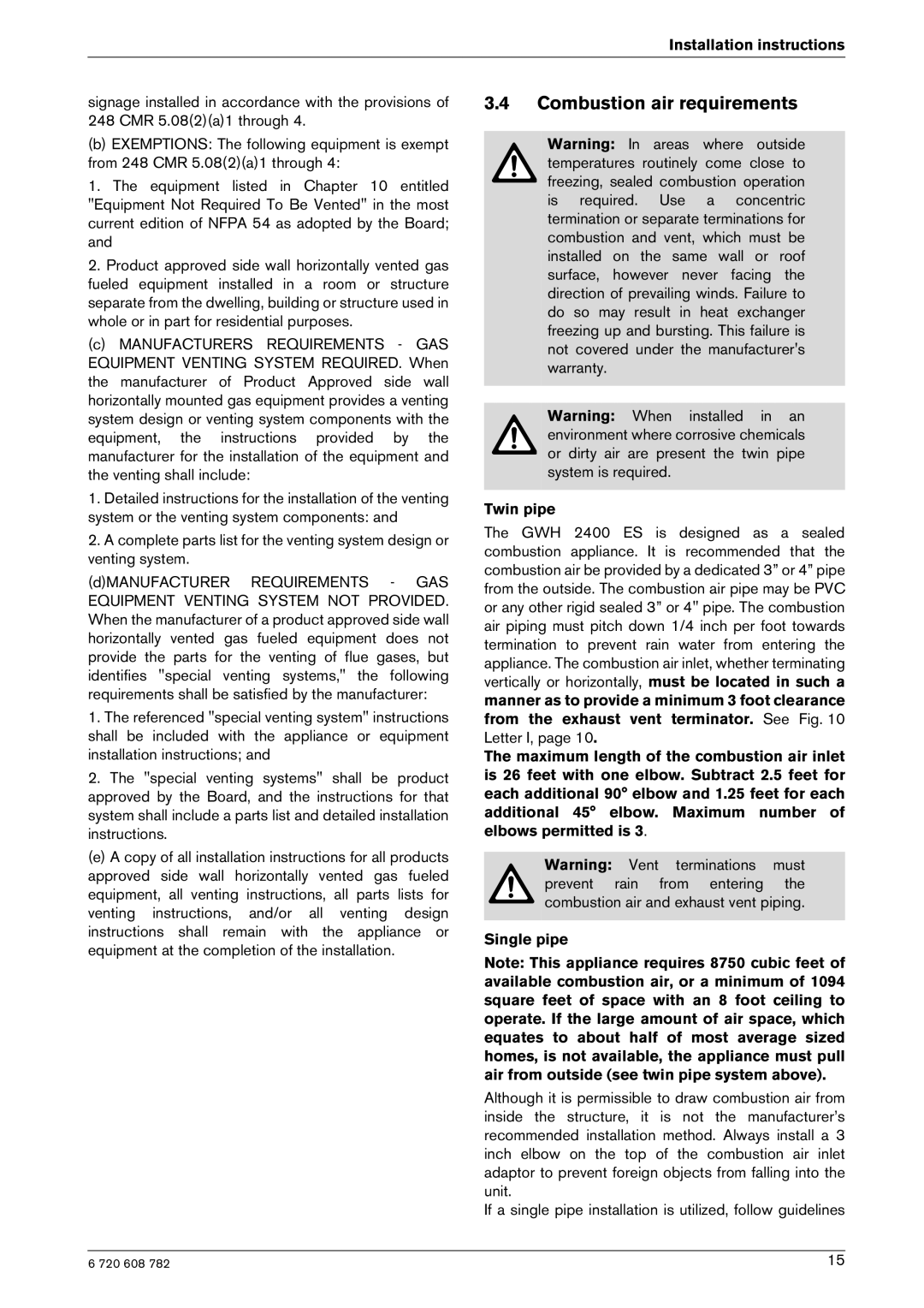
The maximum length of the combustion air inlet is 26 feet with one elbow. Subtract 2.5 feet for each additional 90° elbow and 1.25 feet for each additional 45° elbow. Maximum number of elbows permitted is 3.

Warning: Vent terminations must prevent rain from entering the combustion air and exhaust vent piping.

Single pipe

Note: This appliance requires 8750 cubic feet of available combustion air, or a minimum of 1094 square feet of space with an 8 foot ceiling to operate. If the large amount of air space, which equates to about half of most average sized homes, is not available, the appliance must pull air from outside (see twin pipe system above).

Although it is permissible to draw combustion air from inside the structure, it is not the manufacturer’s recommended installation method. Always install a 3 inch elbow on the top of the combustion air inlet adaptor to prevent foreign objects from falling into the unit.

If a single pipe installation is utilized, follow guidelines

6 720 608 782

15

Image 15
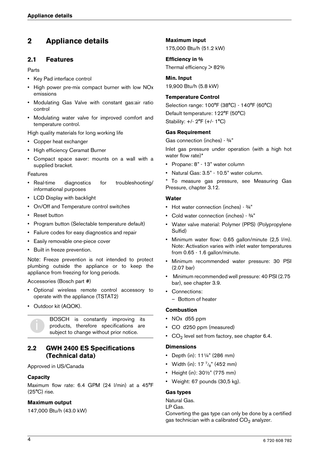
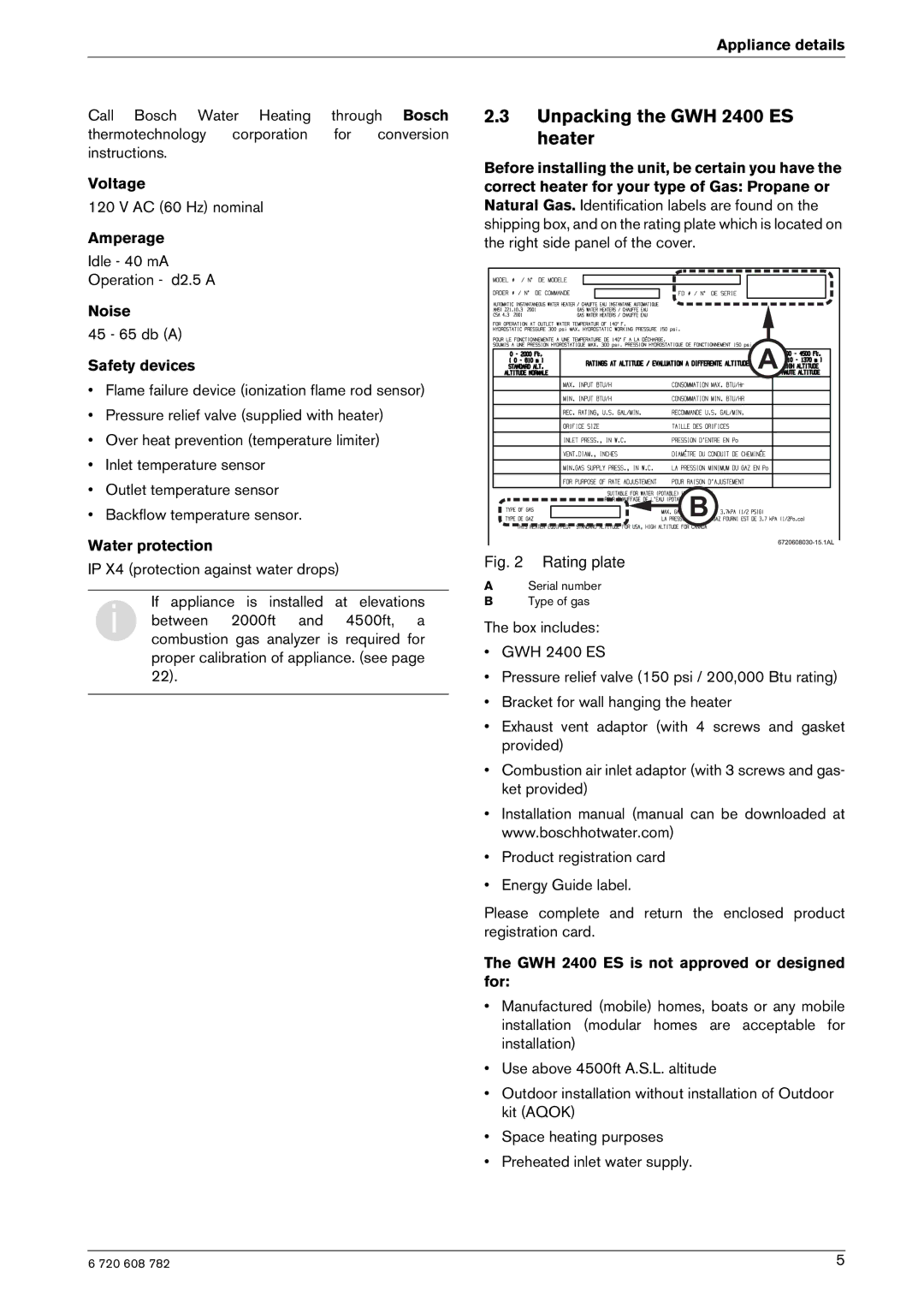
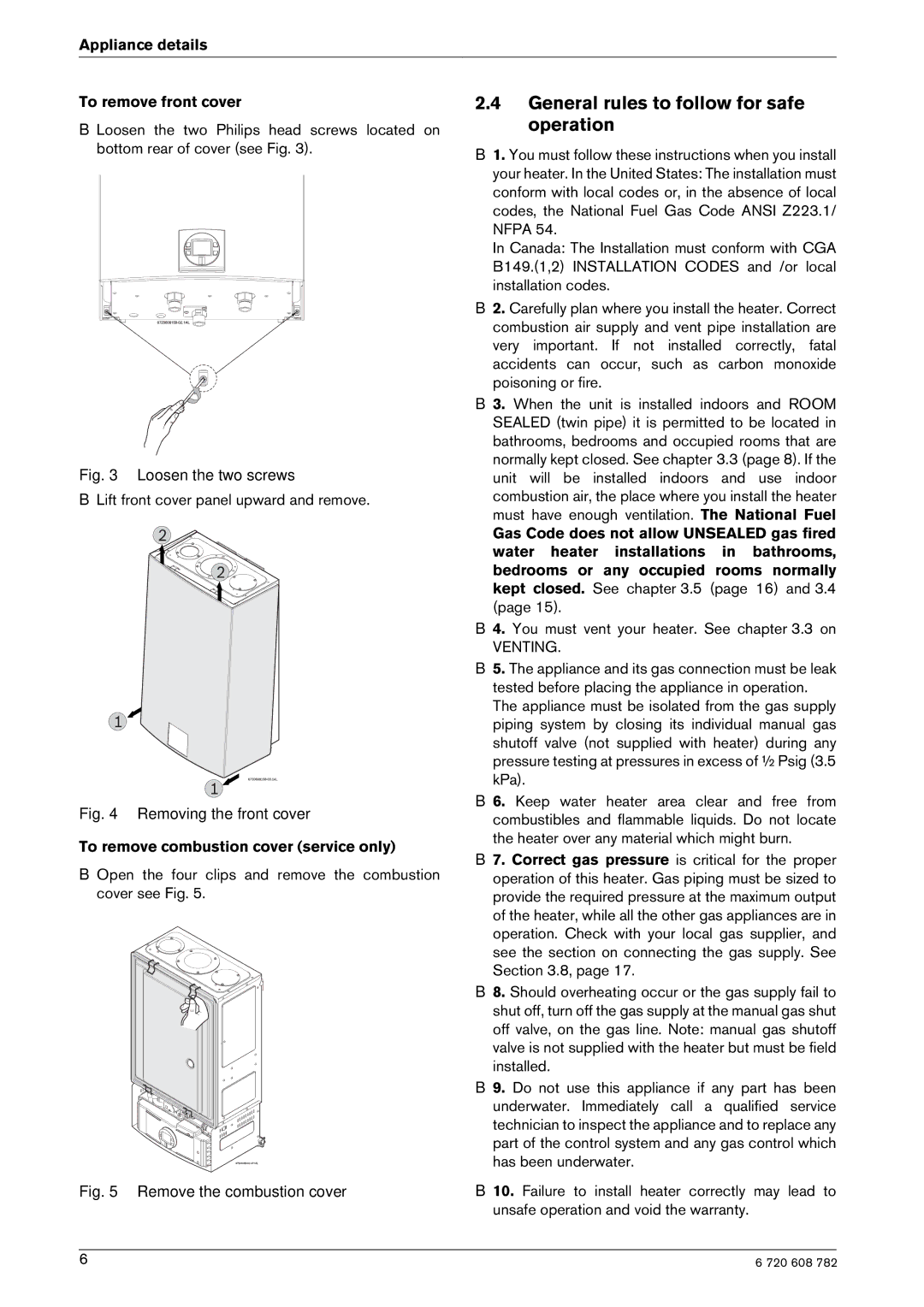
Contents What to do if you smell gas Intended for variable flow applicationsIndex FCC For your safetyFeatures GWH 2400 ES Specifications Technical dataAppliance details Unpacking the GWH 2400 ES heater To remove combustion cover service only General rules to follow for safe operationAppliance details To remove front cover Dimensions Dimensions and Minimum installation clearancesVenting Installation instructionsTools required for installation IntroductionFittings or Piping Equivalent Feet Vent Safety SystemDescription Minimum distance Installation instructions Venting configuration examples Installation instructions Condensate drain requirements Room sealed installation Twin Pipe SystemVenting Flex ProTech Heat Fab Exhaust Determining installation adjustmentInstallation instructions Vent connections Twin pipe Combustion air requirementsProper location for installing your heater Heater placement and clearancesMounting installation Gas piping & connections GAS Connections For Natural GAS Water quality Water connectionsRecirculation application Recirculation applicationMeasuring gas pressure Electrical power supply Electrical connectionsPosition of the fuses in control unit LCD Display functions Operation instructionsFor your safety read before operating your water heater PowerTemperature selection Program button Use of optional remote control accessory part no. TSTAT2Reset button OperationWinterizing for seasonal use Maintenance and serviceAnnual maintenance table Every year Annual maintenanceAdjusting CO2 carbon dioxide Descaling using a pumpMineral scale build-up Once Gas Pressure is adequate Measuring CO2 combustion cover must be installedAdjusting CO2 Returning to Service% 2.8 % 60 ppm Final ReadingsProgram Description Factory Default Program valuesComment Diagnostic menu Control board diagnosticsExample Fan speed adjustmentTotal vent length calculation IntakeMode Pipe Length1 Fan speed Maintenance and service To select fan speedWater is not hot enough TroubleshootingTroubleshooting Water is too hotHot water temperature fluctuates at tap Low water flow/pressureNoisy burner/heater during operation Troubleshooting Error code diagnostics Problem solvingVenting may cause this failure Problem solving Display Cause SolutionOver-temperature detected by No flame ionization detected with Electrical diagram Electrical diagramSensor resistance charts Back Flow characteristics Functional scheme GWH 2400 ES Functional schemeInterior components diagram and parts list Interior components diagram and parts listInterior components Appliance overview Item Description Components diagramGroup Description ReferenceInterior components diagram and parts list Group Interior components diagram and parts list Group Interior components diagram and parts list Group Interior components diagram and parts list Group 708 300 Components Protecting the environmentProtecting the environment PackingLimited Warranty Bosch Thermotechnology Corporation

GWH 2400 ES NG, GWH 2400 ES LP specifications

Bosch Appliances has established a reputation for delivering high-quality and innovative home solutions, and the Bosch GWH 2400 ES LP and GWH 2400 ES NG are no exceptions. These high-efficiency water heaters are designed to provide on-demand hot water, ensuring comfort and convenience for your home.

One of the standout features of the Bosch GWH 2400 ES LP (Liquid Propane) and GWH 2400 ES NG (Natural Gas) models is their compact, space-saving design. These tankless water heaters are engineered to fit in smaller spaces, making them an ideal choice for homes with limited installation areas. Despite their compact size, both models provides a powerful performance that meets the hot water needs for multiple fixtures simultaneously, such as showers, faucets, and washing machines.

These water heaters are equipped with advanced technology that enables precise temperature control. The Bosch GWH 2400 ES series utilizes a microprocessor-based control system that allows for consistent water heating, ensuring the water temperature remains stable even during high demand. The modulating gas valve further optimizes energy consumption, adjusting the flame intensity to meet the exact heating needs, thus enhancing efficiency.

In terms of safety, both the GWH 2400 ES LP and NG come with multiple safety features. These include a flame failure safeguard, overheating protection, and a built-in freeze protection system. Such features ensure both peace of mind and the longevity of the unit.

Installation is straightforward with these models, as they can be vented using standard venting materials, saving time and costs. Additionally, the units boast a low NOx emissions rating, making them environmentally friendly choices that help homeowners reduce their carbon footprint.

Maintenance is minimal, thanks to the corrosion-resistant heat exchanger which ensures durability and long service life under normal operating conditions. This factor, combined with Bosch’s renowned commitment to quality, makes these models a reliable investment for any household.

Whether you opt for the GWH 2400 ES LP or the GWH 2400 ES NG, you will experience the benefits of a powerful, efficient, and safe water heating solution tailored to your specific household needs. Bosch has truly combined technology, sustainability, and user comfort in these innovative models, solidifying their place as leaders in the home appliance market.