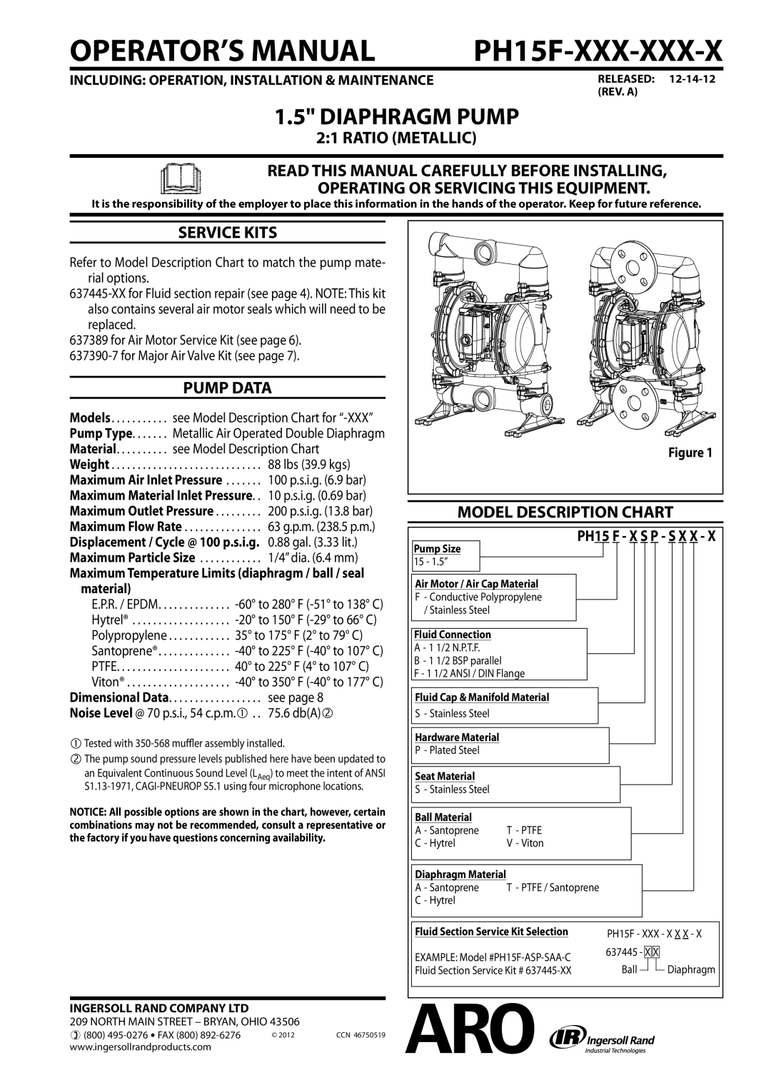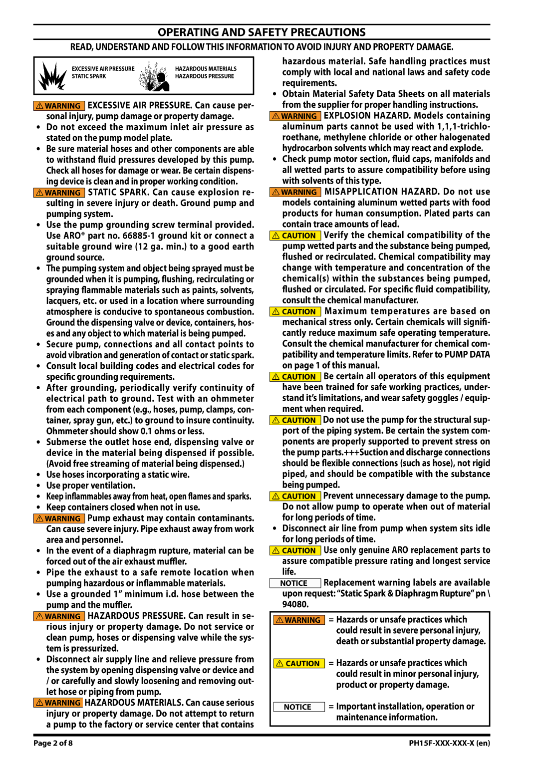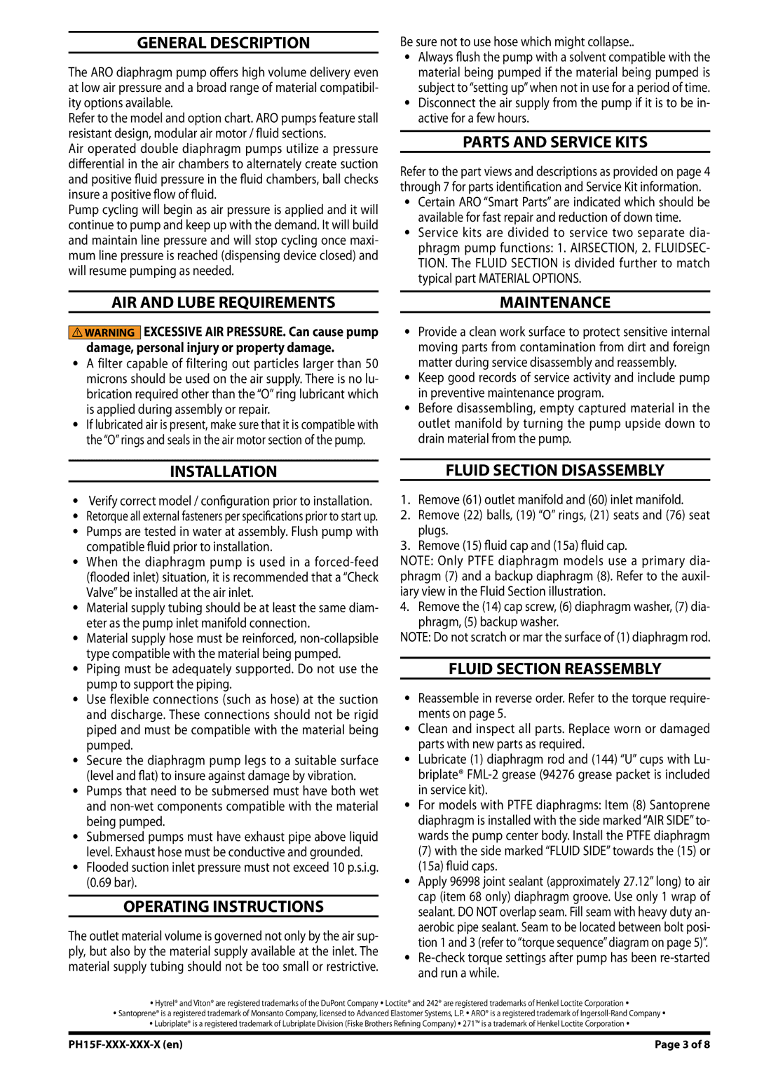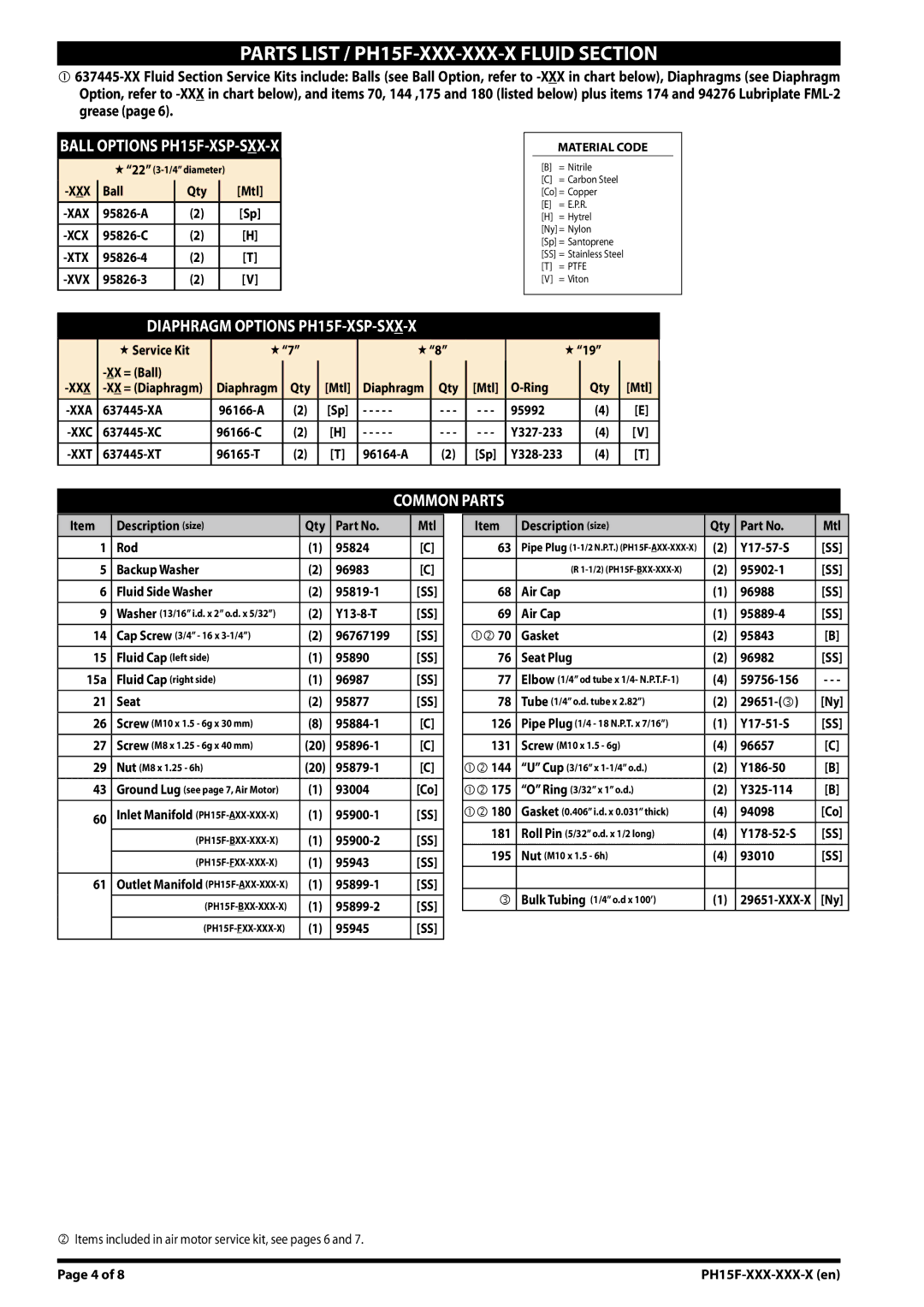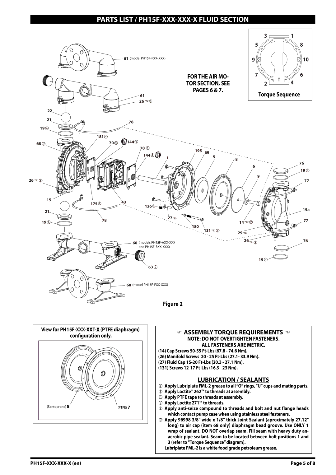
PARTS LIST / PH15F-XXX-XXX-X FLUID SECTION
BALL OPTIONS PH15F-XSP-SXX-X
“22”
Ball | Qty | [Mtl] | |
(2) | [Sp] | ||
(2) | [H] | ||
|
|
|
|
(2) | [T] | ||
|
|
|
|
|
| (2) | [V] |
|
|
|
|
MATERIAL CODE
[B]= Nitrile
[C]= Carbon Steel [Co] = Copper
[E]= E.P.R.
[H]= Hytrel [Ny] = Nylon [Sp] = Santoprene
[SS]= Stainless Steel
[T]= PTFE
[V]= Viton
DIAPHRAGM OPTIONS PH15F-XSP-SXX-X
| Service Kit | “7” |
| “8” |
|
| “19” |
|
| |||
|
|
|
|
|
|
|
| Qty |
| [Mtl] | ||
|
|
|
|
|
|
|
|
| ||||
Diaphragm | Qty | [Mtl] | Diaphragm | Qty | [Mtl] |
|
| |||||
|
|
|
|
|
|
|
|
|
|
|
|
|
(2) | [Sp] | - - - - - | - - - | - - - | 95992 |
| (4) |
| [E] | |||
|
|
|
|
|
|
|
|
|
|
|
|
|
(2) | [H] | - - - - - | - - - | - - - |
| (4) |
| [V] | ||||
(2) | [T] | (2) | [Sp] |
| (4) |
| [T] | |||||
|
|
|
|
|
|
|
|
|
|
|
|
|
COMMON PARTS
Item | Description (size) | Qty | Part No. | Mtl |
|
|
|
|
|
1 | Rod | (1) | 95824 | [C] |
|
|
|
|
|
5 | Backup Washer | (2) | 96983 | [C] |
|
|
|
|
|
6 | Fluid Side Washer | (2) | [SS] | |
|
|
|
|
|
9 | Washer (13/16” i.d. x 2” o.d. x 5/32”) | (2) | [SS] | |
|
|
|
|
|
14 | Cap Screw (3/4” - 16 x | (2) | 96767199 | [SS] |
|
|
|
|
|
15 | Fluid Cap (left side) | (1) | 95890 | [SS] |
|
|
|
|
|
15a | Fluid Cap (right side) | (1) | 96987 | [SS] |
|
|
|
|
|
21 | Seat | (2) | 95877 | [SS] |
|
|
|
|
|
26 | Screw (M10 x 1.5 - 6g x 30 mm) | (8) | [C] | |
|
|
|
|
|
27 | Screw (M8 x 1.25 - 6g x 40 mm) | (20) | [C] | |
|
|
|
|
|
29 | Nut (M8 x 1.25 - 6h) | (20) | [C] | |
|
|
|
|
|
43 | Ground Lug (see page 7, Air Motor) | (1) | 93004 | [Co] |
|
|
|
|
|
60 | Inlet Manifold | (1) | [SS] | |
| (1) | [SS] | ||
|
|
|
|
|
| (1) | 95943 | [SS] | |
|
|
|
|
|
61 | Outlet Manifold | (1) | [SS] | |
|
|
|
|
|
| (1) | [SS] | ||
|
|
|
|
|
| (1) | 95945 | [SS] | |
|
|
|
|
|
Item | Description (size) | Qty | Part No. | Mtl |
|
|
|
|
|
63 | Pipe Plug | (2) | [SS] | |
|
|
|
|
|
| (R | (2) | [SS] | |
|
|
|
|
|
68 | Air Cap | (1) | 96988 | [SS] |
|
|
|
|
|
69 | Air Cap | (1) | [SS] | |
|
|
|
|
|
70 | Gasket | (2) | 95843 | [B] |
|
|
|
|
|
76 | Seat Plug | (2) | 96982 | [SS] |
|
|
|
|
|
77 | Elbow (1/4” od tube x 1/4- | (4) | - - - | |
|
|
|
|
|
78 | Tube (1/4” o.d. tube x 2.82”) | (2) | [Ny] | |
|
|
|
|
|
126 | Pipe Plug (1/4 - 18 N.P.T. x 7/16”) | (1) | [SS] | |
|
|
|
|
|
131 | Screw (M10 x 1.5 - 6g) | (4) | 96657 | [C] |
|
|
|
|
|
144 | “U” Cup (3/16” x | (2) | [B] | |
|
|
|
|
|
175 | “O” Ring (3/32” x 1” o.d.) | (2) | [B] | |
|
|
|
|
|
180 | Gasket (0.406” i.d. x 0.031” thick) | (4) | 94098 | [Co] |
|
|
|
|
|
181 | Roll Pin (5/32” o.d. x 1/2 long) | (4) | [SS] | |
|
|
|
|
|
195 | Nut (M10 x 1.5 - 6h) | (4) | 93010 | [SS] |
|
|
|
|
|
|
|
|
|
|
| Bulk Tubing (1/4” o.d x 100’) | (1) | [Ny] | |
|
|
|
|
|
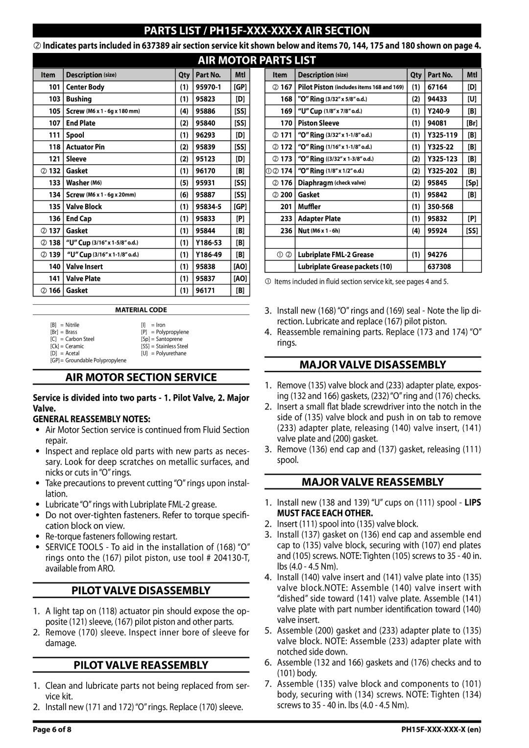
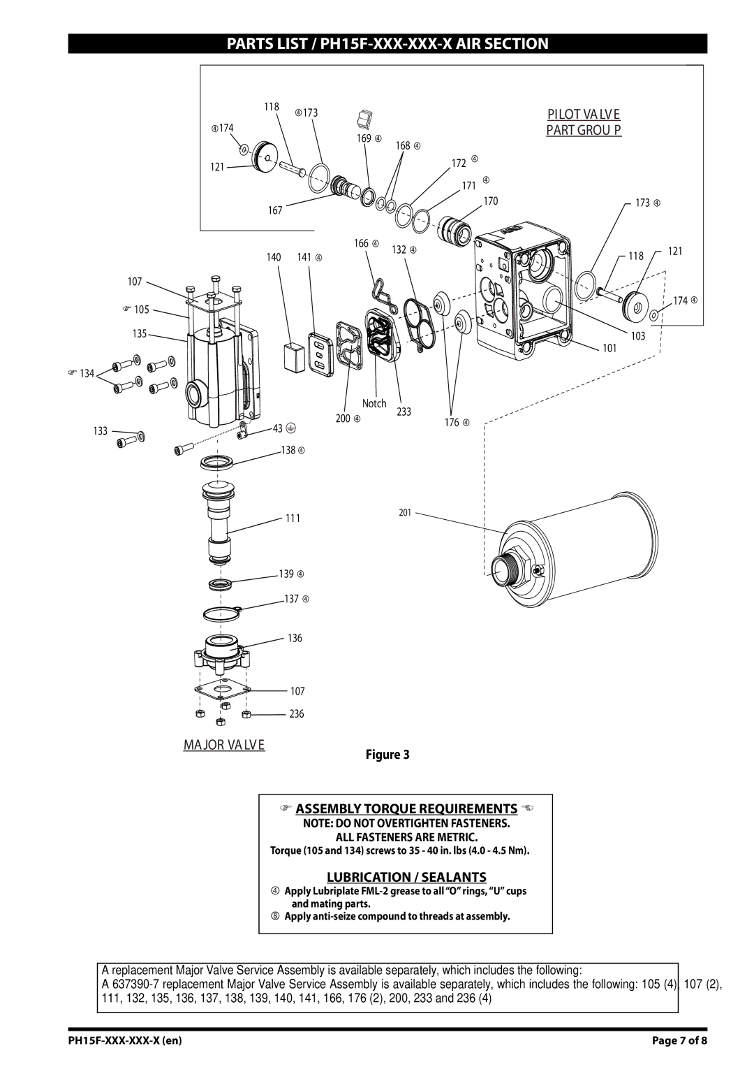
Items included in air motor service kit, see pages 6 and 7.
Page of 8 |
