Lincoln
II - Advantage Series
service manual
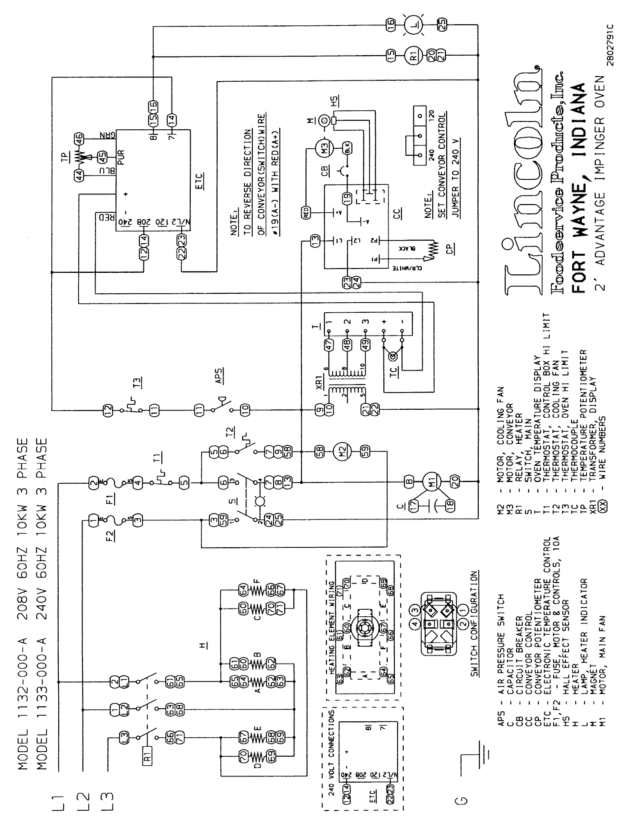
Schematic 1132-000-A / 1133-000-A
Page 7
SCHEMATIC
1132-000-A /
1133-000-A
Impinger II
–Advantage
Service Manual - Domestic
7
Page 6
Page 8
Image 7
Page 6
Page 8
Contents
Impinger Conveyor Ovens
Table of Contents
Impinger II Advantage
Sequence of Operations
Heater Circuit
Control BOX Auto Cool Down
Schematic 1116-000-A, 1117-000-A
Schematic 1130-000-A / 1131-000-A
Schematic 1132-000-A / 1133-000-A
LP GAS
Troubleshooting Guide / GAS Ovens
Phase
Natural GAS
Page
Attached to the Temperature Control
With Power on and Thermocouple Leads
Page
Page
Refer to Proper Schematic for Identified Components
Troubleshooting Guide / Electric Ovens
Single Phase
Three Phase
Leads Attached to the Temperature
With Power on and Thermocouple
Page
Page
FAN, Main
REMOVAL, INSTALLATION, and Adjustment
ON/OFF Switch Replacement
MOTOR, Main FAN
High Limit Thermostat Replacement
Fuse Holder Replacement
THERMOSTAT, Control BOX HI-LIMIT Replacement
Burner Blower Motor Replacement
Information
Burner Transformer Replacement
Thermocouple Replacement
Thermocouple Measurement Chart
Heat Light Replacement
Electronic Temperature Control Board Replacement
Electronic Temperature Control Board Calibration
Temperature Control Potentiometer Replacement
Conveyor Control Potentiometer Replacement
Temperature Regulation Valve Replacement
HOT Surface Ignitor Replacement
Main Burner Orifice Replacement
Circuit Breaker
Conveyor Control Board Replacement
Conveyor Drive Motor Replacement
Conveyor Control Board Calibration
Calibration of Temperature Display
Hall Effect Sensor Replacement
Temperature Display Transformer Replacement
Temperature Display Replacement
BEARING, Conveyor
Heating Element Replacement
This page intentionally left blank
Letter Part Number Description
Parts / General
Blow UP / General
Parts / Control BOX 1116-000-A, 1117-000-A
Blow UP / Control BOX 1116-000-A, 1117-000-A
Parts / Control BOX 1130-000-A Thru 1133-000-A
Blow UP / Control BOX 1130-000-A Thru 1133-000-A
Parts / Conveyor & Door
Blow UP / Conveyor & Door
Parts / Oven Back Assembly
Blow UP / Oven Back Assembly
Related pages
How do I contact support using the
MSI B75A-G43 manual
?
Top
Page
Image
Contents