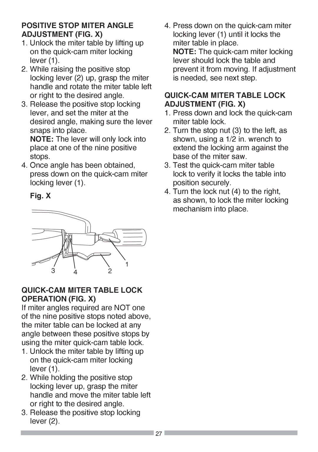
Craftsman 137.37564 manual Crown Molding Chart

Page 39

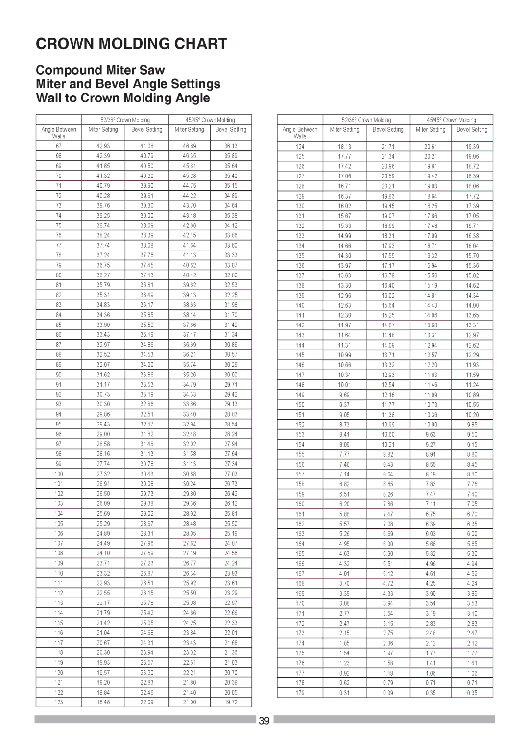
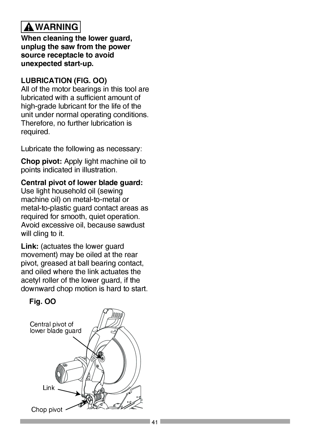
CROWN MOLDING CHART

Compound Miter Saw

Miter and Bevel Angle Settings Wall to Crown Molding Angle


52/38° Crown Molding

45/45° Crown Molding

Angle Between

Miter Setting

Bevel Setting

Miter Setting

Bevel Setting

Walls


67

42.93

41.08

46.89

36.13

68

42.39

40.79

46.35

35.89

69

41.85

40.50

45.81

35.64

70

41.32

40.20

45.28

35.40

71

40.79

39.90

44.75

35.15

72

40.28

39.61

44.22

34.89

73

39.76

39.30

43.70

34.64

74

39.25

39.00

43.18

35.38

75

38.74

38.69

42.66

34.12

76

38.24

38.39

42.15

33.86

77

37.74

38.08

41.64

33.60

78

37.24

37.76

41.13

33.33

79

36.75

37.45

40.62

33.07

80

36.27

37.13

40.12

32.80

81

35.79

36.81

39.62

32.53

82

35.31

36.49

39.13

32.25

83

34.83

36.17

38.63

31.98

84

34.36

35.85

38.14

31.70

85

33.90

35.52

37.66

31.42

86

33.43

35.19

37.17

31.34

87

32.97

34.86

36.69

30.86

88

32.52

34.53

36.21

30.57

89

32.07

34.20

35.74

30.29

90

31.62

33.86

35.26

30.00

91

31.17

33.53

34.79

29.71

92

30.73

33.19

34.33

29.42

93

30.30

32.86

33.86

29.13

94

29.86

32.51

33.40

28.83

95

29.43

32.17

32.94

28.54

96

29.00

31.82

32.48

28.24

97

28.58

31.48

32.02

27.94

98

28.16

31.13

31.58

27.64

99

27.74

30.78

31.13

27.34

100

27.32

30.43

30.68

27.03

101

26.91

30.08

30.24

26.73

102

26.50

29.73

29.80

26.42

103

26.09

29.38

29.36

26.12

104

25.69

29.02

28.92

25.81

105

25.29

28.67

28.48

25.50

106

24.89

28.31

28.05

25.19

107

24.49

27.96

27.62

24.87

108

24.10

27.59

27.19

24.56

109

23.71

27.23

26.77

24.24

110

23.32

26.87

26.34

23.93

111

22.93

26.51

25.92

23.61

112

22.55

26.15

25.50

23.29

113

22.17

25.78

25.08

22.97

114

21.79

25.42

24.66

22.66

115

21.42

25.05

24.25

22.33

116

21.04

24.68

23.84

22.01

117

20.67

24.31

23.43

21.68

118

20.30

23.94

23.02

21.36

119

19.93

23.57

22.61

21.03

120

19.57

23.20

22.21

20.70

121

19.20

22.83

21.80

20.38

122

18.84

22.46

21.40

20.05

123

18.48

22.09

21.00

19.72


52/38° Crown Molding

45/45° Crown Molding

Angle Between

Miter Setting

Bevel Setting

Miter Setting

Bevel Setting

Walls


124

18.13

21.71

20.61

19.39

125

17.77

21.34

20.21

19.06

126

17.42

20.96

19.81

18.72

127

17.06

20.59

19.42

18.39

128

16.71

20.21

19.03

18.06

129

16.37

19.83

18.64

17.72

130

16.02

19.45

18.25

17.39

131

15.67

19.07

17.86

17.05

132

15.33

18.69

17.48

16.71

133

14.99

18.31

17.09

16.38

134

14.66

17.93

16.71

16.04

135

14.30

17.55

16.32

15.70

136

13.97

17.17

15.94

15.36

137

13.63

16.79

15.56

15.02

138

13.30

16.40

15.19

14.62

139

12.96

16.02

14.81

14.34

140

12.63

15.64

14.43

14.00

141

12.30

15.25

14.06

13.65

142

11.97

14.87

13.68

13.31

143

11.64

14.48

13.31

12.97

144

11.31

14.09

12.94

12.62

145

10.99

13.71

12.57

12.29

146

10.66

13.32

12.20

11.93

147

10.34

12.93

11.83

11.59

148

10.01

12.54

11.46

11.24

149

9.69

12.16

11.09

10.89

150

9.37

11.77

10.73

10.55

151

9.05

11.38

10.36

10.20

152

8.73

10.99

10.00

9.85

153

8.41

10.60

9.63

9.50

154

8.09

10.21

9.27

9.15

155

7.77

9.82

8.91

8.80

156

7.46

9.43

8.55

8.45

157

7.14

9.04

8.19

8.10

158

6.82

8.65

7.83

7.75

159

6.51

8.26

7.47

7.40

160

6.20

7.86

7.11

7.05

161

5.88

7.47

6.75

6.70

162

5.57

7.08

6.39

6.35

163

5.26

6.69

6.03

6.00

164

4.95

6.30

5.68

5.65

165

4.63

5.90

5.32

5.30

166

4.32

5.51

4.96

4.94

167

4.01

5.12

4.61

4.59

168

3.70

4.72

4.25

4.24

169

3.39

4.33

3.90

3.89

170

3.08

3.94

3.54

3.53

171

2.77

3.54

3.19

3.10

172

2.47

3.15

2.83

2.83

173

2.15

2.75

2.48

2.47

174

1.85

2.36

2.12

2.12

175

1.54

1.97

1.77

1.77

176

1.23

1.58

1.41

1.41

177

0.92

1.18

1.06

1.06

178

0.62

0.79

0.71

0.71

179

0.31

0.39

0.35

0.35

39

Image 39
Contents Page Warranty Table of ContentsProduct Specifications MotorMiter SAW Prohibition SymbolsGeneral Safety Instructions Before Using this Power Tool Power Tool SafetyAlways Wear EYE Wear Hearing ! DangerSpecific Safety Instructions for this Compound Miter SAW Dual Bevel Compound Miter SAW SafetyPage Power Supply and Motor Specifications Grounding InstructionsGuidelines for Extension Cords Adapter Receptacle Recommended Accessories Accessories and AttachmentsTools Needed for Assembly SuppliedNot suppliedCombination Square Must be True Carton Contents Know Your Dual Bevel Compound Miter SAW Glossary of Terms Revolutions PER Minute RPM Woodworking TermsCutting Head FIG. B AssemblyInstalling the Miter Handle FIG. a Installing the Dust BAG FIG. CInstalling the Extension Wing Assembly FIG. D Installing the Safety HOLD- Down Clamp FIG. FSAW Blade Wrench FIG. E Removing and Installing the Blade Inserting and Replacing the Laser Batteries FIG. GRemoving Blade Fig. H, I, J, K Page Fig. M Mounting the Miter SAWBevel Stop Adjustment AdjustmentsFig. P Right Bevel Positive Stop Adjustment Fig. Q Fig. S Left Bevel Adjustment Fig. T Right Bevel Adjustment Fig. SMiter Angle Adjustment FIG. V, W Miter Scale Indicator FIG. WSquaring the Fence FIG. U Positive Stop Miter Angle Adjustment FIG QUICK-CAM Miter Table Lock Adjustment FIGQUICK-CAM Miter Table Lock Operation FIG Operation Assembly and Adjustments SectionsRequirements and Safety Sections Before Each USE Recommended AccessoriesDress for Safety Plan Your WorkInspect Your Workpiece USE Extra Caution with Large or ODD Shaped Workpieces When SAW is RunningDo not Overreach Never cut freehandBasic SAW Operations Body and Hand Position FIG. YFinishing a cut Before freeing jammed materialFig. Z-2 Sliding Fence FIG. BB To Turn SAW on FIG. AABefore Leaving the SAW Miter CUT FIG. CCBevel CUT FIG. DD Cutting Bowed Material FIG. GG Compound CUT FIG. FF Fig. JJ Cutting Crown Moulding FIG. KK, LL Bevel/Miter SettingsFig. MM Changing the Belt FIG. MMCrown Molding Chart Lower Blade Guard MaintenanceMaintenance Replacing Carbon Brushes FIG. NNFig. OO Lubrication FIG. OOOr Installing Troubleshooting GuideEYE Protection Model no Parts ListParts List for Miter SAW Part a 12 IN. Dual Bevel Compound Miter SAWDescription Size Q’ty I.D. Description Parts List for Miter SAW Part BX635 X636 X637 X62T X63A X639 X63B Description Size ’ty Parts List and Schematic for MotorHere’s what the Repair Protection Agreement* includes Repair Protection AgreementsSears Parts & Repair Service Center SU-HOGARLE-FOYERMC