Connecting the System
Connecting the power cord (1)
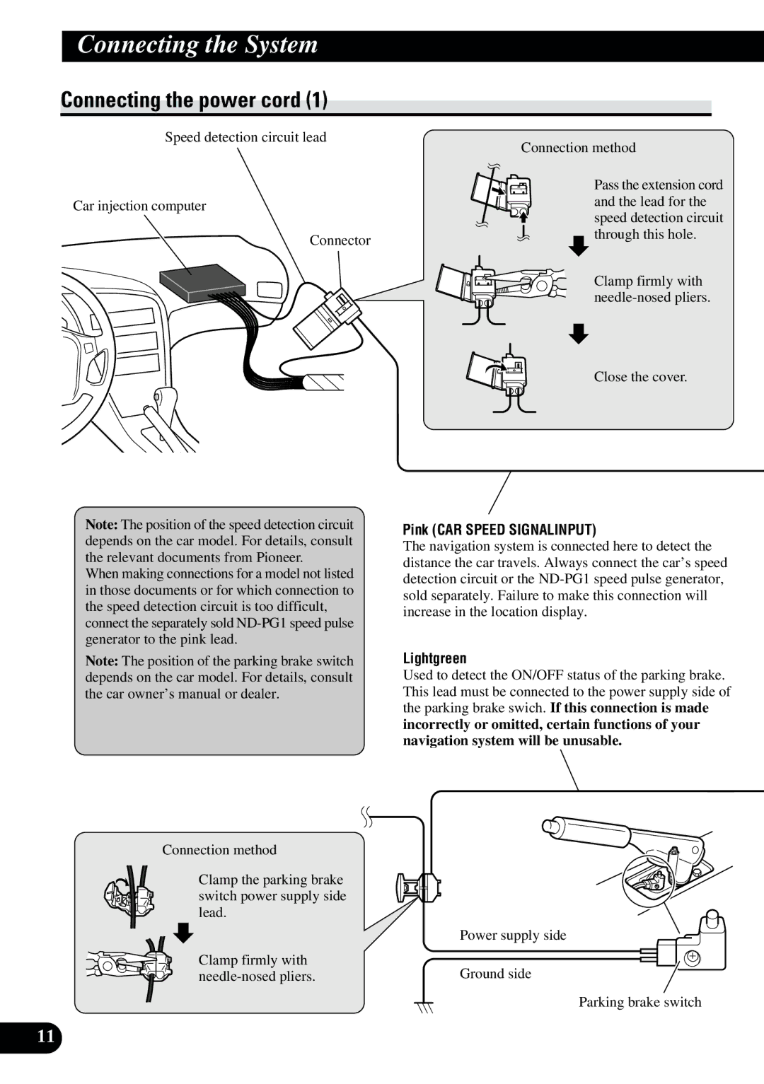
Speed detection circuit lead
Car injection computer
Connector
Note: The position of the speed detection circuit depends on the car model. For details, consult the relevant documents from Pioneer.
When making connections for a model not listed in those documents or for which connection to the speed detection circuit is too difficult, connect the separately sold
Note: The position of the parking brake switch depends on the car model. For details, consult the car owner’s manual or dealer.
Connection method
Clamp the parking brake switch power supply side lead.
Clamp firmly with
11
Connection method
Pass the extension cord and the lead for the speed detection circuit through this hole.
Clamp firmly with
Close the cover.
Pink (CAR SPEED SIGNALINPUT)
The navigation system is connected here to detect the distance the car travels. Always connect the car’s speed detection circuit or the
Lightgreen
Used to detect the ON/OFF status of the parking brake. This lead must be connected to the power supply side of the parking brake swich. If this connection is made incorrectly or omitted, certain functions of your navigation system will be unusable.
Power supply side
Ground side
Parking brake switch