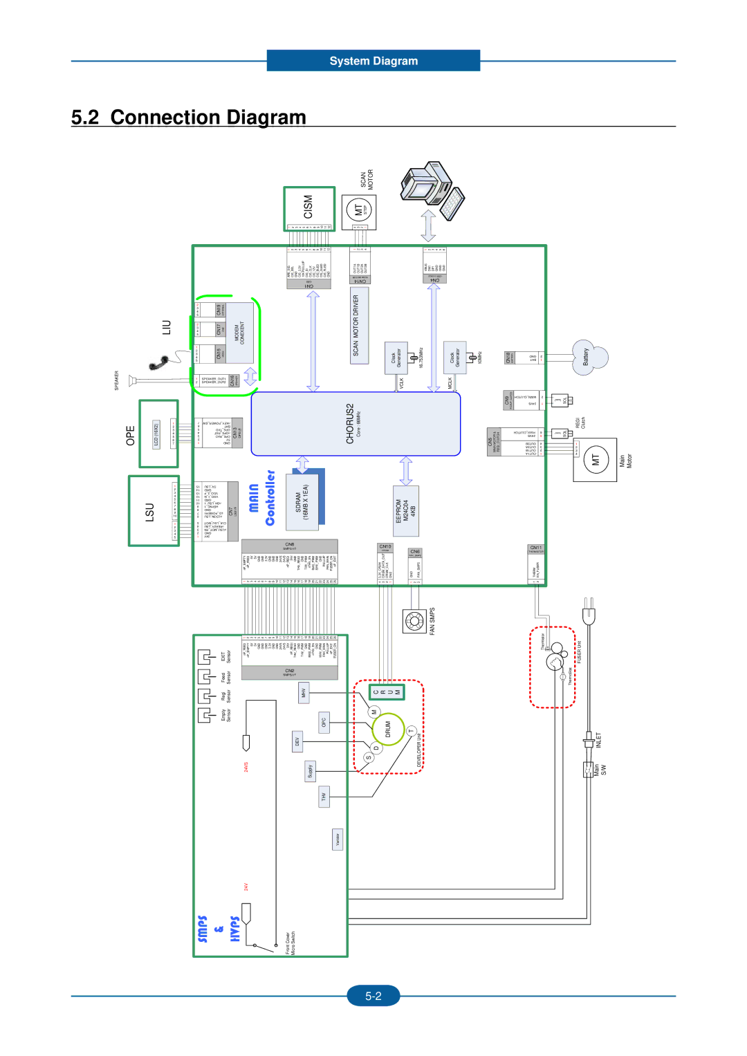
System Diagram

5.2 Connection Diagram


SCAN MOTOR


CISM


MT STEP


1 2 3 4 5 6 7 8 9 10 11 12


4 3 2 1


123456789101112

CISCISCISCISCISCISCISCIS AFE_GND10K___GND _____ SIGSEL3.3VPULLUPSICLK12VBLEDGLEDRLED

CIS

CN1

1234

OUT1AOUT1BOUT2AOUT2B

MOTOR SCAN CN14

123456

VBUSDM1DP1GNDGNDGND

DEVICE USB

CN4

LIU

SPEAKER

OPE

LCD (16X2)

1

2

3

4

5

6

7

2

CN19

EXTERNAL


3


4


5


2

CN17


MODEM CONEXENT

3

LINE

4

5


1

CN15


2

HOOK


3


4


5


1

SPEAKER_OUT1


CN16 SPEAKER


2

SPEAKER_OUT2


7


SW_POWER_nKEY


6


BAT

CN13 OPEI/F


3


RXD_OPE


5


OPE _ TXD


4


RST_nOPE


2


5V


1


GND


DRIVERMOTOR

SCAN

:Core CHORUS266MHz

Clock Generator


16.753MHz


VCLK


Clock Generator


10MHz


CN18

BATTERY

GND

2


BAT

1


MCLK


CN9 CLUTCHPICKUP

CLUTCH_MAIN


24VS


CN5 MOTORMAIN & REGICLUTCH


CLUTCH_REGI

6


OUT1B

2


24VS

5


OUT2B

4


OUT2A

3


OUT1A

1

Battery


SOL


REGI Clutch


SOL


1


2


3

MT


4

Main Motor


1


2


3


4


LSU

5


6


7


8


9


10


1


2


3


4


5


15 14 13 12 11 10 9 8 7 6

5 4 3 2 1

LSU_5V GND P_2_VDO N_1_VDO GND 1_LSU_nSH 1_HSYNC GND POWER1_LD LSU_nLDON

MOT_LSU_CLK LSU_nREADY EN_MOT_nLSU GND 24V

CN7 LSU I/F

MAIN Controller


SDRAM (16MB X 1EA)


CN8


SMPS I/F


nP EMPTY nP FEED 5V 5V GND GND 3.3V GND GND GND 24VS 24VS nP REGI

24V

GND THV READ GND THV PWM nTHV EN BIAS PWM MHV PWM GND PULLUP FAN MAIN FUSER ON nP EXIT


1 2 3 4 5 6 7 8 9 10 11 12 13 14

15

16 17 18 19 20 21 22 23 24 25 26


EEPROM M24C04 4KB


CN10


CRUM


CN6

3.3V CRUM CRUM DATA OUT CRUM CLK GND


FAN_SMPS


GND FAN SMPS

4 3 2 1


1 2 3


CN11

THERMISTOR

THERM

EN_FUSER


1 2


Empty Regi Feed EXIT Sensor Sensor Sensor Sensor

1234567891011121314151617181920212223242526

nP _THV nPnP_THVBIASMHVFANnP ____ _nTHV___ _FUSER FEEDEMPTY5V5VGNDGNDGND3.3VGNDGND24VS24VS24VREGIREADGNDPWMGNDPWMENGNDPWMMAINPULLUPEXITON

CN2

SMPS I/F

MHV

FAN SMPS

Thermistor

C R U M

M

FUSER Unit

ThermoStat

SMPS & HVPS

24VS

24V

DEV

Micro Switch

Front Cover

OPC

Supply

THV

Varistor

DRUM

T Unit

S D

DEVELOPER

Main INLET S/W

5-2

Page 138
Image 138
2Wire F-116P manual Connection Diagram, MT Step

F-116P, F-116 specifications

The 2Wire F-116 and F-116P are prominent models in the digital home networking market, specifically designed to cater to the needs of both residential and small business users. These devices combine advanced technology with user-friendly features, making them a popular choice among consumers seeking reliable connectivity.

At the heart of the F-116 and F-116P is their commitment to providing robust wireless connectivity. Both models operate on dual-band technology, allowing them to transmit signals on both 2.4 GHz and 5 GHz frequencies. This dual-band capability helps reduce congestion and interference, ensuring smoother performance for devices that demand higher bandwidth, such as streaming boxes and gaming consoles.

The F-116 and F-116P are equipped with multiple Ethernet ports, allowing users to connect several devices simultaneously. This feature is particularly advantageous for homes or offices with multiple wired devices, facilitating stable connections for desktops, printers, and smart TVs. The addition of USB ports further expands their functionality, enabling the connection of external storage devices for network sharing, or printers for easy access throughout the network.

Another standout feature of these models is their support for advanced security protocols. They bolster network security with WPA2 encryption, ensuring that user data remains secure from unauthorized access. The inclusion of a firewall adds an extra layer of protection, providing robust defense against malicious attacks.

The F-116P model enhances the user experience with the inclusion of Powerline networking capabilities. This technology utilizes existing electrical wiring in the home to extend the network's reach, allowing users to achieve internet connectivity in hard-to-reach areas without the need for additional cabling.

Moreover, both models come with intuitive web-based interfaces for easy setup and management. Users can customize settings, monitor network traffic, and manage connected devices effortlessly. The device’s compatibility with various ISPs ensures that users can easily integrate them into their existing setups.

In summary, the 2Wire F-116 and F-116P offer a blend of performance, security, and user-friendly features that make them ideal for consumers looking to enhance their home or office networks. Their dual-band technology, multiple connectivity options, advanced security, and innovative Powerline capabilities position them as versatile solutions in an increasingly connected world.