TRSM Components | 13 |
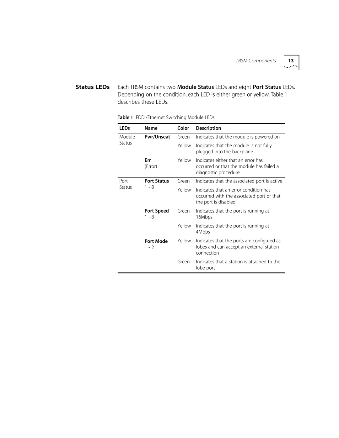
Status LEDs Each TRSM contains two Module Status LEDs and eight Port Status LEDs. Depending on the condition, each LED is either green or yellow. Table 1 describes these LEDs.
Table 1 FDDI/Ethernet Switching Module LEDs
LEDs | Name | Color | Description |
|
|
|
|
Module | Pwr/Unseat | Green | Indicates that the module is powered on |
Status |
| Yellow | Indicates that the module is not fully |
|
| ||
|
|
| plugged into the backplane |
| Err | Yellow | Indicates either that an error has |
| (Error) |
| occurred or that the module has failed a |
|
|
| diagnostic procedure |
Port | Port Status |
Status | 1 - 8 |
Green | Indicates that the associated port is active |
Yellow | Indicates that an error condition has |
| occurred with the associated port or that |
| the port is disabled |
Port Speed 1 - 8
Port Mode 1 - 2
Green | Indicates that the port is running at |
| 16Mbps |
Yellow | Indicates that the port is running at |
| 4Mbps |
Yellow | Indicates that the ports are configured as |
| lobes and can accept an external station |
| connection |
Green | Indicates that a station is attached to the |
| lobe port |
