3D Connexion RET-1500, RET-2000, RET-2500 owner manual Assembly

Models: RET-2000 RET-1500 RET-2500

1 15
Download 15 pages 33.68 Kb
Page 8
Image 8

RET Series

4.3 Assembly

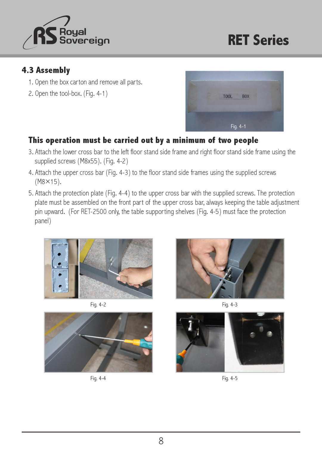
1.Open the box carton and remove all parts.

2.Open the tool-box. (Fig. 4-1)

Fig. 4-1

This operation must be carried out by a minimum of two people

3.Attach the lower cross bar to the left floor stand side frame and right floor stand side frame using the supplied screws (M8x55). (Fig. 4-2)

4.Attach the upper cross bar (Fig. 4-3) to the floor stand side frames using the supplied screws (M8×15).

5.Attach the protection plate (Fig. 4-4) to the upper cross bar with the supplied screws. The protection plate must be assembled on the front part of the upper cross bar, always keeping the table adjustment pin upward. (For RET-2500 only, the table supporting shelves (Fig. 4-5) must face the protection panel)

Fig. 4-2


Fig. 4-3


Fig. 4-4

Fig. 4-5

8

Page 8
Image 8
3D Connexion RET-1500, RET-2000, RET-2500 owner manual Assembly