ZTS Series
Dimensional Specifications / Power Connection Terminals
|
|
|
| ZTS Model Transfer Switches |
|
|
|
|
|
|
|
|
|
|
|
|
|
|
|
|
|
|
|
|
|
|
| ||||||||||||
Ampere |
|
|
| NEMA 1 Enclosed |
|
|
|
|
|
|
|
|
|
|
|
|
|
| Weight |
|
|
|
|
|
|
|
|
|
|
|
|
|
|
| |||||
| Poles | Height | Width |
| Depth | Reference |
|
|
| Open |
|
|
|
|
| Application Notes |
|
|
|
| |||||||||||||||||||
Rating |
|
|
|
|
|
|
| NEMA 1 |
|
|
|
| |||||||||||||||||||||||||||
|
| (A) | (B) |
| (C) | Figure |
|
|
| Type |
|
|
|
|
|
|
|
|
|
|
|
|
|
|
| ||||||||||||||
|
|
|
|
|
|
|
|
|
|
|
|
|
|
|
|
|
|
|
|
|
|
|
|
| |||||||||||||||
40, 80 |
| 2, 3 | 24 (61) | 18 (46) |
| 11.13 | (28) |
| A |
|
| 21 | (10) | 57 (26) | 1 – 7 |
|
|
|
| ||||||||||||||||||||
100, 150 |
| 4 | 24 (61) | 18 (46) |
| 11.13 | (28) |
| A |
|
| 24 | (11) | 60 (27) |
|
|
|
| |||||||||||||||||||||
|
|
|
|
|
|
|
|
|
|
|
|
|
|
|
|
|
| ||||||||||||||||||||||
|
|
|
|
|
|
|
|
|
|
|
|
|
|
|
|
|
|
|
|
|
|
|
|
|
|
|
|
|
|
|
|
|
|
|
|
|
|
|
|
225 |
| 2, 3 | 46 (117) | 24 (61) |
| 14.13 | (36) |
| A |
|
| 70 | (32) | 165 | (75) | 1 – 7 |
|
|
|
| |||||||||||||||||||
260, 400 |
| 4 | 46 (117) | 24 (61) |
| 14.13 | (36) |
| A |
|
| 75 | (34) | 170 | (68) |
|
|
|
| ||||||||||||||||||||
|
|
|
|
|
|
|
|
|
|
|
|
|
|
|
|
|
| ||||||||||||||||||||||
|
|
|
|
|
|
|
|
|
|
|
|
|
|
|
|
|
|
|
|
|
|
|
|
|
|
|
|
|
|
|
|
|
|
|
|
|
| ||
600 |
| 2, 3 | 66 (168) | 24 (61) |
| 19.75 | (50) |
| B |
|
| 165 (75) | 380 (172) | 1 – 8 |
|
|
|
| |||||||||||||||||||||
| 4 | 74 (188) | 30 (76) |
| 19.75 | (50) |
| B |
|
| 185 (84) | 430 (195) |
|
|
|
| |||||||||||||||||||||||
|
|
|
|
|
|
|
|
|
|
|
|
|
|
|
|
|
|
| |||||||||||||||||||||
|
|
|
|
|
|
|
|
|
|
|
|
|
|
|
|
|
|
|
|
|
|
|
|
|
|
|
|
|
|
|
|
|
|
|
|
|
| ||
800, 1000, 1200 |
| 2, 3 | 74 (188) | 30 (76) |
| 19.75 | (50) |
| B |
|
| 190 (86) | 455 (206) | 1 – 8 |
|
|
|
| |||||||||||||||||||||
| 4 | 74 (188) | 40 (102) |
| 19.75 | (50) |
| B |
|
| 210 (95) | 540 (245) |
|
|
|
| |||||||||||||||||||||||
|
|
|
|
|
|
|
|
|
|
|
|
|
|
|
|
|
|
| |||||||||||||||||||||
|
|
|
|
|
|
|
|
|
|
|
|
|
|
|
|
|
|
|
|
|
|
|
|
|
|
|
|
|
|
|
|
|
|
|
|
|
|
| |
1600 |
| 3 | 90 (229) | 30 (76) |
| 48 (122) |
| C |
|
| 345 | (156) | 1010 | (458) | 1 – 8 |
|
|
|
| ||||||||||||||||||||
2000 |
| 4 | 90 (229) | 36 (91) |
| 48 (122) |
| C |
|
| 450 | (204) | 1160 | (526) |
|
|
|
| |||||||||||||||||||||
|
|
|
|
|
|
|
|
|
|
|
|
|
|
|
|
|
| ||||||||||||||||||||||
|
|
|
|
|
|
|
|
|
|
|
|
|
|
|
|
|
|
|
|
|
|
|
|
|
|
|
|
|
|
|
|
|
|
|
|
|
|
| |
3000 |
| 3 | 90 (229) | 30 (76) |
| 48 (122) |
| C |
|
| 465 | (211) | 1130 | (513) | 1 – 10 |
|
|
|
| ||||||||||||||||||||
| 4 | 90 (229) | 36 (91) |
| 48 (122) |
| C |
|
| 670 | (304) | 1395 | (633) |
|
|
|
| ||||||||||||||||||||||
|
|
|
|
|
|
|
|
|
|
|
|
|
|
|
|
|
|
| |||||||||||||||||||||
|
|
|
|
|
|
|
|
|
|
|
|
|
|
|
|
|
|
|
|
|
|
|
|
|
|
|
|
|
|
|
|
|
|
|
|
|
|
| |
4000 |
| 3 | 90 (229) | 40 (102) |
| 60 (152) |
| C |
|
| 770 | (349) | 1595 | (723) | 1 – 10 |
|
|
|
| ||||||||||||||||||||
| 4 | 90 (229) | 46.5 (118) |
| 60 (152) |
| C |
|
| 1025 (465) | 1850 | (839) |
|
|
|
| |||||||||||||||||||||||
|
|
|
|
|
|
|
|
|
|
|
|
|
|
|
|
|
|
| |||||||||||||||||||||
Application Notes: |
|
|
|
|
|
|
|
|
|
|
|
|
|
|
|
|
|
|
|
|
|
|
|
|
|
|
|
| C |
|
|
|
|
|
|
|
|
| |
1. Metric dimensions (cm) and weights (Kg) shown in parenthesis adjacent |
|
|
|
| C |
|
|
|
|
|
|
|
|
|
|
| B |
|
|
|
|
|
|
|
|
|
|
|
|
|
| B | |||||||
|
|
|
|
|
|
|
|
|
|
|
|
|
|
|
|
|
|
|
|
|
|
|
|
|
|
|
|
|
|
|
|
| |||||||
to English measurements in inches and pounds. |
|
|
|
|
|
|
|
|
|
|
|
|
|
|
|
|
|
|
|
|
|
|
|
|
|
|
|
|
|
|
|
|
|
|
|
| |||
2. Includes 1.25" door projection beyond base depth. Allow a minimum of 3" |
|
|
|
|
|
|
|
|
|
|
|
|
|
|
|
|
|
|
|
|
|
|
|
|
|
|
|
|
|
|
|
|
| ||||||
additional depth for projection of handle, light, switches, pushbuttons, etc. |
|
|
|
|
|
|
|
|
|
|
|
|
|
|
|
|
|
|
|
|
|
|
|
|
|
|
|
|
|
|
|
|
| ||||||
3. All dimensions and weights are approximate and subject to change |
|
|
|
|
|
|
|
|
|
|
|
|
|
|
|
|
|
|
|
|
|
|
|
|
|
|
|
|
|
|
|
|
|
| |||||
without notice. |
|
|
|
|
|
|
|
|
|
|
|
|
| A |
|
|
|
|
|
|
|
|
|
|
|
|
|
|
|
| A |
|
|
|
| ||||
4. Special enclosures (NEMA 3R, 4, 12, etc.) dimensions and layout may differ. |
|
|
|
|
|
|
|
|
|
|
|
|
|
|
|
|
|
|
|
|
|
|
|
|
|
|
| ||||||||||||
|
|
|
|
|
|
|
|
|
|
|
|
|
|
|
|
|
|
|
|
|
|
|
|
|
|
|
|
|
|
|
| ||||||||
Consult the GE Zenith factory for details. |
|
|
|
|
|
|
|
|
|
|
|
|
|
|
|
|
|
|
|
|
|
|
|
|
|
|
|
|
|
|
|
|
|
|
|
| |||
5.Normal and emergency may be ordered inverted on any switch.
The load may be inverted
6. | Special lug arrangements may require different enclosure dimensions. |
|
|
|
|
|
| |
|
|
|
|
| ||||
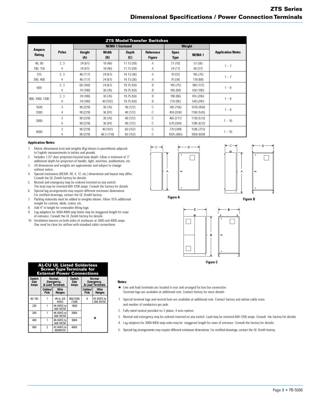
| For certified drawings, contact the GE Zenith factory. | Figure A | Figure B | |||||
7. | Packing materials must be added to weights shown. Allow 15% additional | |||||||
|
| |||||||
weight for cartons, skids, crates, etc.
8.Add 4" in height for removable lifting lugs.
9.Lug adapters for
of entrance. Consult the GE Zenith factory for details.
10.Ventilation louvers on both sides of enclosure at 3000 and 4000 amps. One must be clear for airflow with standard cable connections.
Figure C
External Power Connections
Switch | Normal, | Switch | Normal | ||
Size | Emergency, | Size | Emergency, | ||
Amps | & Load Terminals | Amps | & Load Terminals | ||
| Cables/ | Wire |
| Cables/ | Wire |
| Pole | Ranges |
| Pole | Ranges |
1 | #8 to 3/0 | 800/1000 | 4 | #2 AWG to | |
|
| AWG | /1200 |
| 600 MCM |
225 | 1 | #4 AWG to | 1600 |
|
|
|
| 600 MCM |
|
|
|
260 | 1 | #4 AWG to | 2000 |
|
|
|
| 600 MCM |
|
| * |
400 | 1 | #4 AWG to | 3000 |
| |
|
| 600 MCM |
|
| |
600 | 2 | #2 AWG to | 4000 |
|
|
|
| 600MCM |
|
|
|
Notes:
*Line and load terminals are located in rear and arranged for bus bar connection. Terminal lugs are available at additional cost. Contact factory for more details.
1.Special terminal lugs and neutral bars are available at additional cost. Contact factory and advise cable sizes and number of conductors per pole.
2.Fully rated neutral provided on 3 phase, 4 wire system.
3.Normal and emergency may be ordered inverted on any switch. Load may be inverted
4.Lug adapters for
5.Special lug arrangements may require different enclosure dimensions. For certified drawings, contact the GE Zenith factory.
Page 9 •