ZTS Series
Automatic Transfer Switches
Electrical Ratings
•Ratings 40 to 4000 amperes
•2, 3 or 4 Poles
•Open type, NEMA 1, 3R, 4, 4X and 12
•Available to 600 VAC, 50 or 60 Hz
•Suitable for emergency and standby applications on all classes of load, 100% tungsten rated through 400 amps
•UL 1008 listed at 480 VAC
•CSA C22.2 No. 178 certified at 600 VAC
•IEC
Performance Features
•Contact transfer speed less than 100 milliseconds
•High close-in and withstand capability
•Temperature rise test per UL 1008 conducted after overload and endurance tests - exceeds UL requirements
•Available in ZTS (utility- generator), ZTSU (utility- utility), ZTSG (generator- generator) and ZTSM (manual) configurations
Design and Construction Features
• | Double throw, |
| interlocked operation |
• | Electrically operated, |
| mechanically held by a |
| simple, |
| mechanism |
• | Segmented silver tungsten |
| alloy contacts with |
| separate arcing contacts |
| on 225 amp and above |
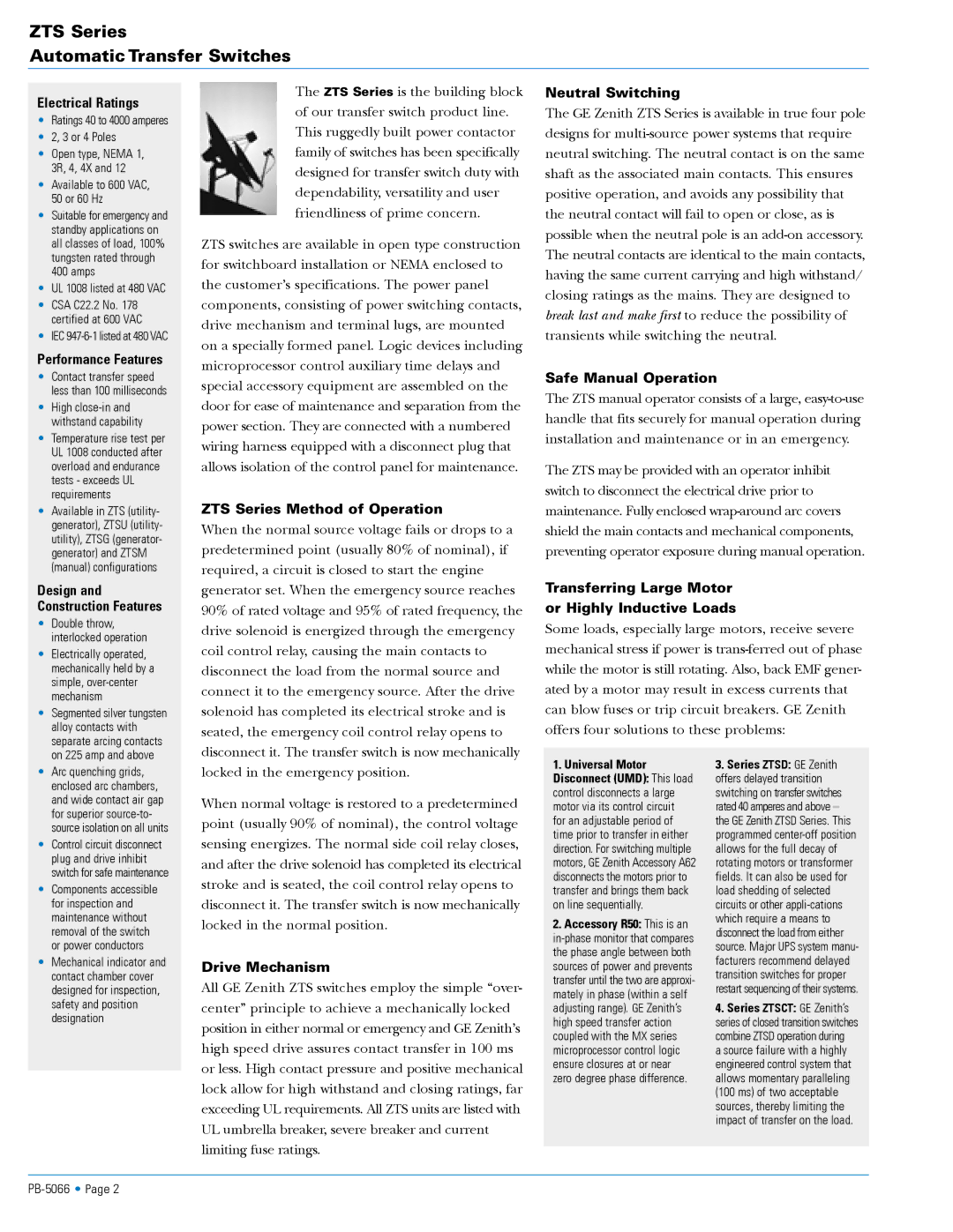
The ZTS Series is the building block of our transfer switch product line. This ruggedly built power contactor family of switches has been specifically designed for transfer switch duty with dependability, versatility and user friendliness of prime concern.
ZTS switches are available in open type construction for switchboard installation or NEMA enclosed to the customer’s specifications. The power panel components, consisting of power switching contacts, drive mechanism and terminal lugs, are mounted on a specially formed panel. Logic devices including microprocessor control auxiliary time delays and special accessory equipment are assembled on the door for ease of maintenance and separation from the power section. They are connected with a numbered wiring harness equipped with a disconnect plug that allows isolation of the control panel for maintenance.
ZTS Series Method of Operation
When the normal source voltage fails or drops to a predetermined point (usually 80% of nominal), if required, a circuit is closed to start the engine generator set. When the emergency source reaches 90% of rated voltage and 95% of rated frequency, the drive solenoid is energized through the emergency coil control relay, causing the main contacts to disconnect the load from the normal source and connect it to the emergency source. After the drive solenoid has completed its electrical stroke and is seated, the emergency coil control relay opens to disconnect it. The transfer switch is now mechanically
Neutral Switching
The GE Zenith ZTS Series is available in true four pole designs for
Safe Manual Operation
The ZTS manual operator consists of a large,
The ZTS may be provided with an operator inhibit switch to disconnect the electrical drive prior to maintenance. Fully enclosed
Transferring Large Motor
or Highly Inductive Loads
Some loads, especially large motors, receive severe mechanical stress if power is
• | Arc quenching grids, |
| enclosed arc chambers, |
| and wide contact air gap |
| for superior |
| source isolation on all units |
• | Control circuit disconnect |
| plug and drive inhibit |
| switch for safe maintenance |
• | Components accessible |
| for inspection and |
| maintenance without |
| removal of the switch |
| or power conductors |
• | Mechanical indicator and |
| contact chamber cover |
| designed for inspection, |
| safety and position |
| designation |
locked in the emergency position.
When normal voltage is restored to a predetermined point (usually 90% of nominal), the control voltage sensing energizes. The normal side coil relay closes, and after the drive solenoid has completed its electrical stroke and is seated, the coil control relay opens to disconnect it. The transfer switch is now mechanically locked in the normal position.
Drive Mechanism
All GE Zenith ZTS switches employ the simple “over- center” principle to achieve a mechanically locked position in either normal or emergency and GE Zenith’s high speed drive assures contact transfer in 100 ms or less. High contact pressure and positive mechanical lock allow for high withstand and closing ratings, far exceeding UL requirements. All ZTS units are listed with UL umbrella breaker, severe breaker and current limiting fuse ratings.
1.Universal Motor Disconnect (UMD): This load control disconnects a large motor via its control circuit for an adjustable period of time prior to transfer in either direction. For switching multiple motors, GE Zenith Accessory A62 disconnects the motors prior to transfer and brings them back on line sequentially.
2.Accessory R50: This is an
3.Series ZTSD: GE Zenith offers delayed transition switching on transfer switches rated 40 amperes and above – the GE Zenith ZTSD Series. This programmed
4.Series ZTSCT: GE Zenith’s series of closed transition switches combine ZTSD operation during
a source failure with a highly engineered control system that allows momentary paralleling (100 ms) of two acceptable sources, thereby limiting the impact of transfer on the load.