GAS SUPPLY CONNECTIONS

GAS SUPPLY PIPE CONNECTIONS

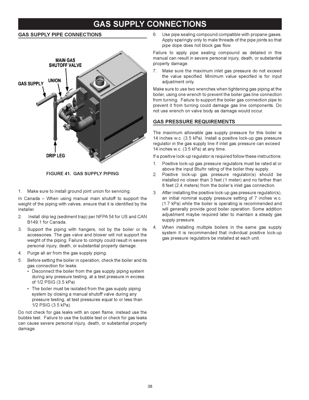
Figure 41.  GAS SUPPLY PIPING

1.Make sure to install ground joint union for servicing.

In Canada – When using manual main shutoff to support the weight of the piping with valves, ensure that it is identified by the installer.

2.Install drip leg (sediment trap) per NFPA 54 for US and CAN B149.1 for Canada.

3.Support the piping with hangers, not by the boiler or its accessories. The gas valve and blower will not support the weight of the piping. Failure to comply could result in severe personal injury, death, or substantial property damage.

4.Purge all air from the gas supply piping.

5.Before setting the boiler in operation, check the boiler and its gas connection for leaks.

Disconnect the boiler from the gas supply piping system during any pressure testing, at a test pressure in excess of 1/2 PSIG (3.5 kPa)

The boiler must be isolated from the gas supply piping system by closing a manual shutoff valve during any pressure testing, at test pressures equal to or less than 1/2 PSIG (3.5 kPa).

Do not check for gas leaks with an open flame, instead use the bubble test. Failure to use the bubble test or check for gas leaks can cause severe personal injury, death, or substantial property damage.

6.Use pipe sealing compound compatible with propane gases. Apply sparingly only to male threads of the pipe joints so that pipe dope does not block gas flow.

Failure to apply pipe sealing compound as detailed in this manual can result in severe personal injury, death, or substantial property damage.

7.Make sure the maximum inlet gas pressure do not exceed the value specified. Minimum value specified is for input adjustment only.

Make sure to use two wrenches when tightening gas piping at the boiler, using one wrench to prevent the boiler gas line connection from turning. Failure to support the boiler gas connection pipe to prevent it from turning could damage gas line components. Do not use wrench on valve body as damage would occur.

GAS PRESSURE REQUIREMENTS

The maximum allowable gas supply pressure for this boiler is 14 inches w.c. (3.5 kPa). Install a positive lock-up gas pressure regulator in the gas supply line if inlet gas pressure can exceed 14 inches w.c. (3.5 kPa) at any time.

If a positive lock-up regulator is required follow these instructions:

1.Positive lock-up gas pressure regulators must be rated at or above the input Btu/hr rating of the boiler they supply.

2.Positive lock-up gas pressure regulator(s) should be installed no closer than 3 feet (1 meter) and no farther than 8 feet (2.4 meters) from the boiler’s inlet gas connection.

3.After installing the positive lock-up gas pressure regulator(s), an initial nominal supply pressure setting of 7 inches w.c. (1.7 kPa) while the boiler is operating is recommended and will generally provide good boiler operation. Some addition adjustment maybe required later to maintain a steady gas supply pressure.

4.When installing multiple boilers in the same gas supply system it is recommended that individual positive lock-up gas pressure regulators be installed at each unit.

38

Page 38
Image 38
A.O. Smith 1700, 3400, 2600, 2000 GAS Supply Connections, GAS Supply Pipe Connections, GAS Pressure Requirements

3400, 1700, 2000, 2600 specifications

A.O. Smith, a leader in water heating solutions, has developed a range of high-efficiency water heaters that cater to various residential and commercial needs. Among their stellar offerings are the A.O. Smith 2600, 2000, 1700, and 3400 models, each boasting impressive features, cutting-edge technologies, and excellent energy efficiency.

The A.O. Smith 2600 model is designed for those who require a robust water heating solution with a capacity to handle high-demand scenarios. It utilizes a highly efficient heating element that provides rapid heating and maintains a steady output. The built-in smart control system allows users to monitor temperature settings and track energy consumption, ensuring optimal performance.

Next in line, the A.O. Smith 2000 is perfect for households that require a reliable and efficient water heater without compromising on space. This compact model integrates advanced thermal insulation that minimizes heat loss, coupled with a powerful heating element that ensures quick heating times. Its sleek design makes it suitable for various installations while maintaining aesthetic appeal.

The A.O. Smith 1700 model caters specifically to smaller residential needs but retains features that align with higher-end models. It incorporates state-of-the-art safety features, including overheat protection and a pressure relief valve. Its lightweight structure and ease of installation stand out, making it a recommended choice for those looking for efficient heating without extensive modifications to their plumbing systems.

Lastly, the A.O. Smith 3400 is a powerhouse designed for larger commercial applications. This model offers exceptional heating capacities and includes advanced technologies such as a digital display for easy monitoring and control. The robust build is complemented by a high-performance insulation system that significantly reduces energy consumption and operating costs.

All A.O. Smith water heaters, including the 2600, 2000, 1700, and 3400 models, feature corrosion-resistant materials ensuring longevity and durability. With their commitment to quality and innovation, A.O. Smith continues to provide water heating solutions that meet modern demands while emphasizing energy efficiency and user convenience. Whether for residential or commercial use, each model represents the pinnacle of reliability and performance in water heating technology.

In conclusion, A.O. Smith has established itself as a reliable choice for water heaters, with models that cater to diverse needs without compromising on efficiency or quality.