INSTALLATION
 WARNING
FOR CALIFORNIA INSTALLATION THIS WATER HEATER MUST BE BRACED,ANCHORED,ORSTRAPPEDTOAVOIDFALLINGORMOVING DURING AN EARTHQUAKE. SEE INSTRUCTIONS FOR CORRECT INSTALLATIONPROCEDURES. INSTRUCTIONSMAYBEOBTAINEDFROM YOUR LOCAL DEALER, WHOLESALER, PUBLIC UTILITIES OR CALIFORNIA'S OFFICE OF THE STATE ARCHITECT, 400 P STREET, SACRAMENTO, CA 95814.
REQUIRED ABILITY
INSTALLATIONORSERVICEOFTHISWATERHEATERREQUIRESABILITY EQUIVALENT TO THAT OF A LICENSED TRADESMAN IN THE FIELD INVOLVED. PLUMBINGANDELECTRICALWORKAREREQUIRED.
GENERAL
The installation must conform to these instructions, the local code authority having jurisdiction, and the requirements of the power company. In the absence of code requirements follow NFPA-70 (current edition), The National Electrical Code which may be ordered from: National Fire Protection Association, 1 Batterymarch Park, Quincy, MA 02269.
WATER HEATER LOCATION
A minimum clearance of 4" must be allowed for access to replaceable parts such as the thermostats, drain valve and relief valve.
Adequate clearance for servicing this appliance should be considered before installation, such as changing the anodes, etc.
The water heater should be located as close to or centralized to the water piping system as possible. The water heater should be located in an area not subject to freezing temperatures.
 CAUTION
THEHEATERSHOULDBELOCATEDINANAREAWHERELEAKAGEOF THE TANK OR CONNECTIONS WILL NOT RESULT IN DAMAGE TO THE AREA ADJACENT TO THE HEATER OR TO LOWER FLOORS OF THE STRUCTURE. When such locations cannot be avoided, a suitable drain pan piped to an adequate drain should be installed under the heater. Such pans should have a minimum length and width of at least 2 inches greater than the diameter of the heater and should be piped to an adequate drain. Drain pans suitable for these heaters are available from your distributor or Water Products Company, 5621 W. 115th Street, Alsip, IL 60803, or at www.hotwater.com/parts.
Under no circumstances is the manufacturer to be held liable for any water damage in connection with this water heater.
HEATERS WITHOUT DRAIN VALVES:
For convenience of service, it is recommended that a drain valve be installed in the inlet piping, as close to the heater as possible, see page 2.
 WARNING
ANELECTRICALGROUNDISREQUIREDTOREDUCERISKOFELECTRIC SHOCKORPOSSIBLEELECTROCUTION. THEGROUNDSCREWATTHE JUNCTIONBOXISFORBONDINGTHEHEATERTOAGROUNDEDSERVICE ENTRANCE CONDUCTOR, A GROUNDED SERVICE ENTRANCE RACEWAY,ORANEARTHGROUNDINGELECTRODECONDUCTOR.
WATER CONNECTIONS
See page 2 for typical installation. Make sure a suitable pipe thread sealant is used to prevent leakage.
TEMPERATURE AND PRESSURE RELIEF VALVE
A NEW TEMPERATURE AND PRESSURE RELIEF VALVE COMPLYING WITH THE STANDARD FOR RELIEF VALVES FOR HOT WATER SUPPLY SYSTEMS, ANSI Z21.22 MUST BE INSTALLED IN THE HEATER IN THE MARKEDOPENINGPROVIDED. THEVALVEMUSTBEOFASIZE(INPUT RATING) THAT WILL BE ADEQUATE FOR YOUR SIZE HEATER.
Check the metal tag on the relief valve and compare it to the heater’s rating plate. The pressure rating of the relief valve must not exceed the working pressure shown on the rating plate of the heater and the hourly Btu rated temperature steam discharge capacity of the relief valve shall not be less than the input rating of the heater. (Watts x 3.415 = Btu/hr. rate) NO VALVE IS TO BE PLACED BETWEEN THE RELIEF VALVE AND TANK. DO NOT PLUG THE RELIEF VALVE.
The drain line connected to this valve must not contain a reducing coupling or other restriction and should terminate near a suitable drain to prevent water damage during valve operation. Discharge line shall be installed to allow complete drainage of both the valve and line. DO NOT THREAD, PLUGORCAPTHEENDOFTHEDRAINLINE.
CLOSED WATER SYSTEM
A closed system will exist if a back-flow preventer (check valve), pressure reducing valve, or other similar device is installed in the cold water line between the water heater and the street main (or well). Excessive pressure may develop due to the thermal expansion of heated water causing premature tank failure or intermittent relief valve operation. This type of failure is not covered by the limited warranty. An expansion tank or device may be necessary in the cold water supply to alleviate this situation, see page 2. Contact the local plumbing authority.
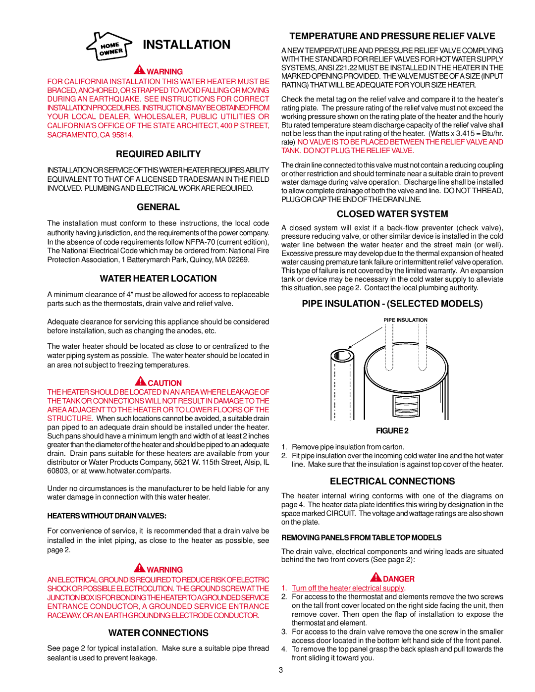
PIPE INSULATION - (SELECTED MODELS)
FIGURE 2
1.Remove pipe insulation from carton.
2.Fit pipe insulation over the incoming cold water line and the hot water line. Make sure that the insulation is against top cover of the heater.
ELECTRICAL CONNECTIONS
The heater internal wiring conforms with one of the diagrams on page 4. The heater data plate identifies this wiring by designation in the space marked CIRCUIT. The voltage and wattage ratings are also shown on the plate.
REMOVING PANELS FROM TABLE TOP MODELS
The drain valve, electrical components and wiring leads are situated behind the two front covers (See page 2):
 DANGER
1.Turn off the heater electrical supply.
2.For access to the thermostat and elements remove the two screws on the tall front cover located on the right side facing the unit, then remove cover. Then open the flap of installation to expose the thermostat and element.
3.For access to the drain valve remove the one screw in the smaller access door located in the bottom left hand side of the front panel.
4.To remove the top panel grasp the back splash and pull towards the front sliding it toward you.