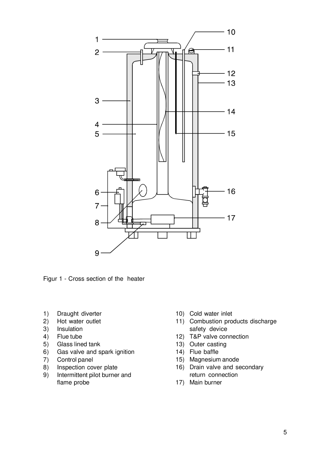
Figur 1 - Cross section of the heater
1) | Draught diverter | 10) | Cold water inlet |
2) | Hot water outlet | 11) | Combustion products discharge |
3) | Insulation |
| safety device |
4) | Flue tube | 12) | T&P valve connection |
5) | Glass lined tank | 13) | Outer casting |
6) | Gas valve and spark ignition | 14) | Flue baffle |
7) | Control panel | 15) | Magnesium anode |
8) | Inspection cover plate | 16) | Drain valve and secondary |
9) | Intermittent pilot burner and |
| return connection |
| flame probe | 17) | Main burner |
5
