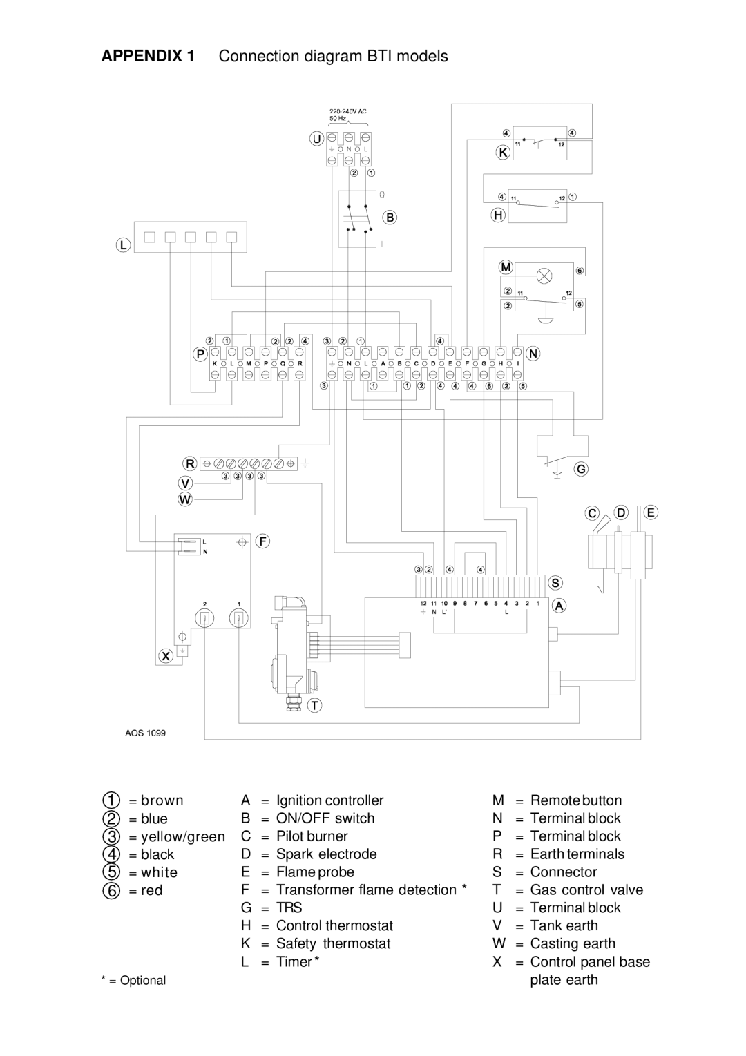
APPENDIX 1 Connection diagram BTI models
1 | = brown | A | = Ignition controller | M | = Remote button |
2 | = blue | B | = ON/OFF switch | N | = Terminal block |
3 | = yellow/green | C | = Pilot burner | P | = Terminal block |
4 | = black | D | = Spark electrode | R | = Earth terminals |
5 | = white | E | = Flame probe | S | = Connector |
6 | = red | F | = Transformer flame detection * | T | = Gas control valve |
|
| G | = TRS | U | = Terminal block |
|
| H | = Control thermostat | V | = Tank earth |
|
| K | = Safety thermostat | W | = Casting earth |
|
| L | = Timer * | X | = Control panel base |
* = Optional |
|
|
| plate earth | |