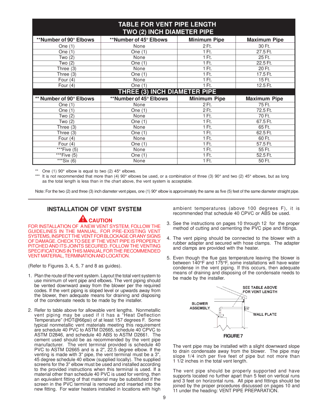
TABLE FOR VENT PIPE LENGTH

TWO (2) INCH DIAMETER PIPE

**Number of 90° Elbows

**Number of 45° Elbows

Minimum Pipe

Maximum Pipe


One (1)

None

2 Ft.

30 Ft.


One (1)

One (1)

1 Ft.

27.5 Ft.


Two (2)

None

1 Ft.

25 Ft.


Two (2)

One (1)

1 Ft.

22.5 Ft.


Three (3)

None

1 Ft.

20 Ft.


Three (3)

One (1)

1 Ft.

17.5 Ft.


Four (4)

None

1 Ft.

15 Ft.


Four (4)

One (1)

1 Ft.

12.5 Ft.


THREE (3) INCH DIAMETER PIPE


** Number of 90° Elbows

**Number of 45° Elbows

Minimum Pipe

Maximum Pipe


One (1)

None

2 Ft.

75 Ft.


One (1)

One (1)

2 Ft.

72.5 Ft.


Two (2)

None

1 Ft.

70 Ft.


Two (2)

One (1)

1 Ft.

67.5 Ft.


Three (3)

None

1 Ft.

65 Ft.


Three (3)

One (1)

1 Ft.

62.5 Ft.


Four (4)

None

1 Ft.

60 Ft.


Four (4)

One (1)

1 Ft.

57.5 Ft.


***Five (5)

None

1 Ft.

55 Ft.


***Five (5)

One (1)

1 Ft.

52.5 Ft.


***Six (6)

None

1 Ft.

50 Ft.


**One (1) 90° elbow is equal to two (2) 45° elbows.

***It is not recommended that more than (4) 90° elbows be used, or a combination of three (3) 90° and two (2) 45° elbows, but as long as the total length is less than in the chart above, the vent system is acceptable.

Note: For the two (2) and three (3) inch diameter vent pipes, one (1) 90° elbow is approximately the same as five (5) feet of the same diameter straight pipe.

INSTALLATION OF VENT SYSTEM

CAUTION

FOR INSTALLATION OF A NEW VENT SYSTEM, FOLLOW THE GUIDELINES IN THE MANUAL. FOR PRE-EXISTING VENT SYSTEMS, INSPECT THE VENT FOR BLOCKAGE ORANY SIGNS OF DAMAGE. CHECK TO SEE IF THE VENT PIPE IS PROPERLY PITCHED AND ITS JOINTS SECURED. FOLLOW THE VENTING SPECIFICATIONS IN THIS MANUAL FOR THE RECOMMENDED VENT MATERIAL, TERMINATIONAND LOCATION.

(Refer to Figures 3, 4, 5, 7 and 8 as guides).

1.Plan the route of the vent system. Layout the total vent system to use minimum of vent pipe and elbows. The vent piping should be vented downward away from the blower per the required codes. If the vent piping is sloped level or upwards away from the blower, then adequate means for draining and disposing of the condensate needs to be made by the installer.

2.Refer to table above for allowable vent lengths. Nonmetallic vent piping may be used if it has a “Heat Deflection Temperature” (HDT@66psi) of at least 157 degrees F. Some typical nonmetallic vent materials meeting this requirement are schedule 40 PVC to ASTM D2665, schedule 40 CPVC to ASTM D2846, and schedule 40 ABS to ASTM D2661. The cement used should be as recommended by the vent pipe manufacturer. The vent terminal provided is schedule 40 PVC to ASTM D2665 and is a 2", 22.5 degree elbow. If the venting is made with 3" pipe, the vent terminal must be a 3", 45 degree schedule 40 elbow (supplied locally). The supplied screens for the 3" elbow must be used and installed according to the provided instructions when this terminal is used. If a material other than schedule 40 PVC is used for venting, then an equivalent fitting of that material may be substituted if the screen in the PVC terminal is removed and inserted into the new fitting. For water heaters installed in locations with high

ambient temperatures (above 100 degrees F), it is recommended that schedule 40 CPVC or ABS be used.

3.See the instructions on pages 10 through 12 for the proper method of cutting and cementing the PVC pipe and fittings.

4.The vent piping should be connected to the blower with a rubber adapter and secured with hose clamps. The adapter and clamps are provided with the heater.

5.Even though the flue gas temperature leaving the blower is between 140°F and 175°F, some installations will have water condense in the vent piping. If this occurs, then adequate means of draining and disposing of the condensate needs to be made by the installer.

FIGURE7

The vent pipe may be installed with a slight downward slope to drain condensate away from the blower. The pipe may slope 1/4 inch per five feet of pipe but not more than 1 1/2 inches in the total vent length.

The vent pipe should be properly supported and have supports located no further apart than 5 feet on vertical runs and 3 feet on horizontal runs. All pipe and fittings should be joined by the proper procedures discussed on pages 10 and 11 under the heading: VENT PIPE PREPARATION.

9

Page 9
Image 9
A.O. Smith GPSH, GPCR owner manual Installation of Vent System, Maximum Pipe

GPCR, GPSH specifications

A.O. Smith has long been a leader in the water heating industry, known for its innovation and commitment to quality. Among its standout products are the GPSH and GPCR series, which exemplify advanced technology and efficiency in water heating solutions.

The GPSH, or Gas Powered Storage Heater, is engineered to optimize energy usage while providing a continuous supply of hot water. This model features advanced thermostatic control, ensuring precise temperature management to meet user needs. Additionally, the GPSH boasts an impressive insulation system, reducing heat loss and resulting in improved energy efficiency. The inclusion of a high-efficiency gas burner allows for faster recovery times, meaning users can enjoy hot water on demand without extended wait times.

On the other hand, the GPCR, or Gas Powered Condensing Revolving Unit, is designed for commercial applications where high demand and energy efficiency are paramount. One of its main features is the condensing technology that recycles flue gases to enhance energy recovery. This leads to significant savings on energy bills and reduced environmental impact. The GPCR's advanced monitoring system provides real-time data on performance and efficiency, allowing for proactive maintenance and management.

Both models come equipped with A.O. Smith's proprietary safety features, including flame rollout switches and temperature and pressure relief valves, ensuring peace of mind for users. Their durable construction employs high-quality materials designed to withstand extreme operating conditions, further promoting longevity.

Installation and maintenance of both the GPSH and GPCR are straightforward, with user-friendly designs that simplify routine checks and servicing tasks. The compact nature of these units means they can fit into a variety of spaces, making them versatile options for both residential and commercial settings.

In summary, A.O. Smith's GPSH and GPCR series represent the pinnacle of water heating technology, combining efficiency, safety, and durability. With a focus on meeting the evolving demands of customers, these products are a reliable choice for anyone seeking effective solutions for their hot water needs. As the industry evolves, A.O. Smith continues to lead the way with its innovative designs and commitment to quality, ensuring users have access to the best water heating solutions available on the market.