GPDT, GPDH, GPDX specifications
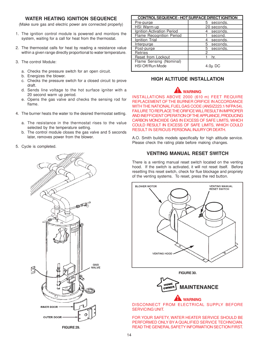
A.O. Smith is a renowned leader in the manufacturing of water heating solutions, and its series of gas water heaters, including the GPDT, GPDH, and GPDX models, are emblematic of the company’s commitment to innovation, efficiency, and reliability.The A.O. Smith GPDT series is characterized by its high energy efficiency and robust design. With a 40-gallon capacity, it utilizes a 0.67 energy factor, making it an ideal choice for both residential and light commercial applications. This model features a unique combustion system that minimizes emissions while maximizing hot water output. Equipped with a powered draft system, the GPDT series effectively vents combustion gases, improving air quality and lowering operational costs.
In contrast, the GPDH series is particularly notable for its compatibility with high-efficiency gas appliances. It employs a direct vent system, allowing for versatile installation options. The GPDH models also include advanced diagnostics and a LED display that simplifies monitoring and maintenance. With an enhanced insulation design, these heaters minimize heat loss, effectively optimizing performance and energy savings.
The GPDX series capitalizes on cutting-edge technologies to provide superior performance. With capacities ranging from 30 to 50 gallons, these water heaters are designed to meet varying needs. The GPDX is equipped with a dual-purpose valve that offers superior temperature control and safety features, ensuring user convenience and peace of mind. Its intuitive interface allows users to easily set their desired water temperature and monitor performance metrics.
One of the key characteristics that unify the GPDT, GPDH, and GPDX models is their commitment to durability. A.O. Smith incorporates high-quality materials and innovative engineering processes to enhance the longevity of their products. Each model features an impressive warranty, demonstrating the company’s confidence in their craftsmanship.
In conclusion, A.O. Smith's GPDT, GPDH, and GPDX gas water heater series offer a blend of efficiency, performance, and innovation. These models are equipped with advanced technologies designed to provide users with reliable hot water solutions while minimizing energy consumption. With their robust build, user-friendly features, and impressive warranties, A.O. Smith continues to be a top choice for those seeking dependable gas water heating solutions.

