Chemical vapor corrosion of the flue, blower assembly and vent system may occur if air for combustion contains certain chemical vapors. Spray can propellants, cleaning solvents, refrigerator and air conditioner refrigerants, swimming pool chemicals, calcium and sodium chloride, waxes, bleach and process chemicals are typical compounds which are potentially corrosive.

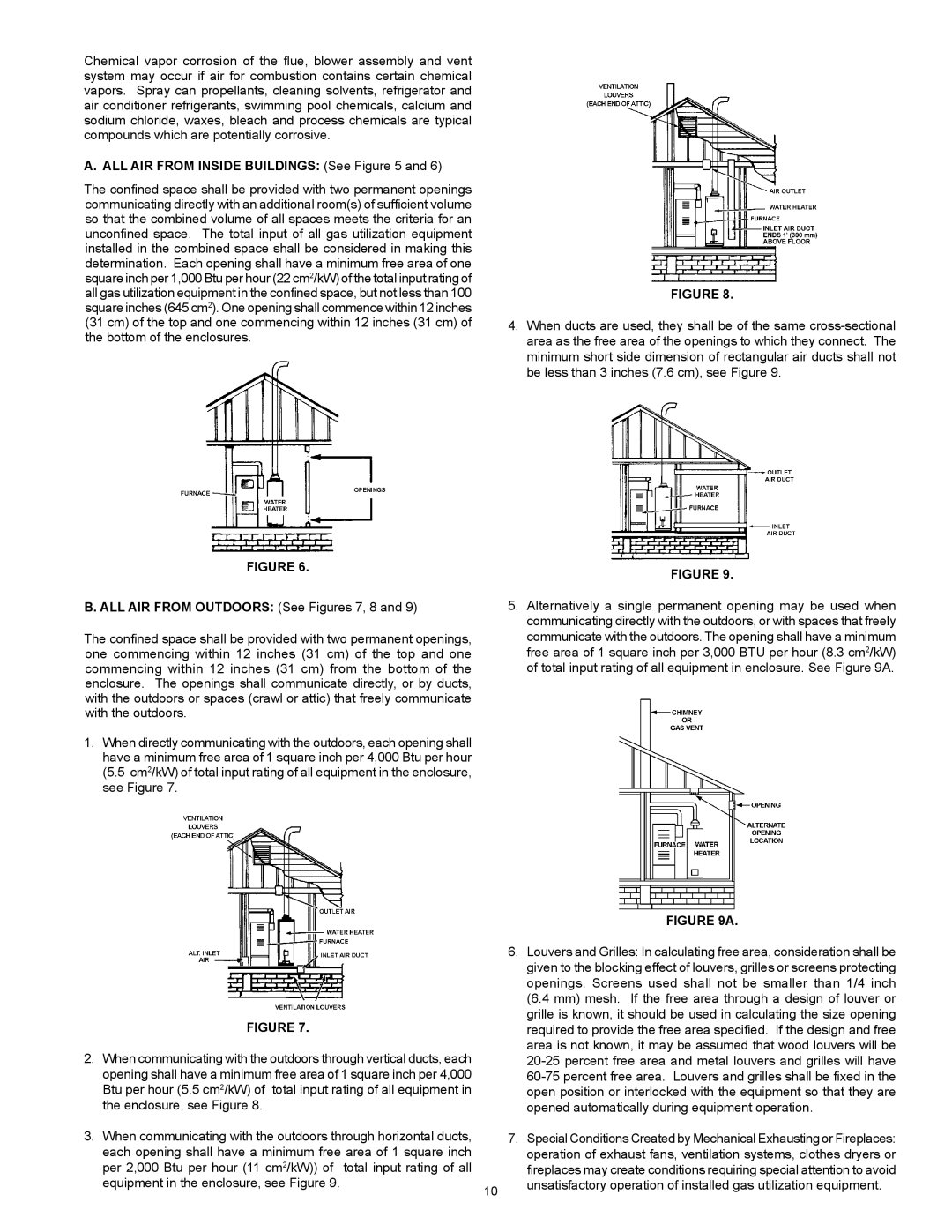
A. ALL AIR FROM INSIDE BUILDINGS: (See Figure 5 and 6)


The confined space shall be provided with two permanent openings


communicating directly with an additional room(s) of sufficient volume


so that the combined volume of all spaces meets the criteria for an


unconfined space. The total input of all gas utilization equipment


installed in the combined space shall be considered in making this


determination. Each opening shall have a minimum free area of one


square inch per 1,000 Btu per hour (22 cm2/kW) of the total input rating of


all gas utilization equipment in the confined space, but not less than 100

FIGURE 8.

square inches (645 cm2). One opening shall commence within 12 inches


(31 cm) of the top and one commencing within 12 inches (31 cm) of

4. When ducts are used, they shall be of the same cross-sectional

the bottom of the enclosures.

area as the free area of the openings to which they connect. The


minimum short side dimension of rectangular air ducts shall not


be less than 3 inches (7.6 cm), see Figure 9.

FIGURE 6.

FIGURE 9.


B. ALL AIR FROM OUTDOORS: (See Figures 7, 8 and 9)

5. Alternatively a single permanent opening may be used when


communicating directly with the outdoors, or with spaces that freely

The confined space shall be provided with two permanent openings,

communicate with the outdoors. The opening shall have a minimum

one commencing within 12 inches (31 cm) of the top and one

free area of 1 square inch per 3,000 BTU per hour (8.3 cm2/kW)

commencing within 12 inches (31 cm) from the bottom of the

of total input rating of all equipment in enclosure. See Figure 9A.

enclosure. The openings shall communicate directly, or by ducts,


with the outdoors or spaces (crawl or attic) that freely communicate


with the outdoors.


1. When directly communicating with the outdoors, each opening shall


have a minimum free area of 1 square inch per 4,000 Btu per hour


(5.5 cm2/kW) of total input rating of all equipment in the enclosure,


see Figure 7.


FIGURE 9A.


6. Louvers and Grilles: In calculating free area, consideration shall be


given to the blocking effect of louvers, grilles or screens protecting


openings. Screens used shall not be smaller than 1/4 inch


(6.4 mm) mesh. If the free area through a design of louver or

FIGURE 7.


grille is known, it should be used in calculating the size opening


required to provide the free area specified. If the design and free

2. When communicating with the outdoors through vertical ducts, each


area is not known, it may be assumed that wood louvers will be


20-25 percent free area and metal louvers and grilles will have

opening shall have a minimum free area of 1 square inch per 4,000


60-75 percent free area. Louvers and grilles shall be fixed in the

Btu per hour (5.5 cm2/kW) of total input rating of all equipment in


open position or interlocked with the equipment so that they are

the enclosure, see Figure 8.


opened automatically during equipment operation.

3. When communicating with the outdoors through horizontal ducts,


7. Special Conditions Created by Mechanical Exhausting or Fireplaces:

each opening shall have a minimum free area of 1 square inch


operation of exhaust fans, ventilation systems, clothes dryers or

per 2,000 Btu per hour (11 cm2/kW)) of total input rating of all


fireplaces may create conditions requiring special attention to avoid

equipment in the enclosure, see Figure 9.

10

unsatisfactory operation of installed gas utilization equipment.


Page 10
Image 10
A.O. Smith GPVR-40 Series 102, GPVX-50, GPVH-50 ALL AIR from Inside Buildings See, ALL AIR from Outdoors See Figures 7, 8

GPVH-50, GPVX-50, GPVR-40 Series 102, GPVR-50, 315465-000 specifications

A.O. Smith is a reputable manufacturer of water heating solutions, and their series of water heaters, particularly models 185237-004, 315465-000, GPVR-50, GPVR-40 Series 102, and GPVX-50, exemplify the company’s commitment to innovation, efficiency, and reliability. These models cater to diverse residential and commercial applications, providing users with versatile options tailored to specific needs.

One of the standout features of these A.O. Smith water heaters is their advanced heating technology. Many of these models, such as the GPVR-50 and GPVR-40 Series 102, are equipped with high-efficiency gas burners designed to maximize thermal efficiency. This ensures that hot water is readily available while minimizing energy consumption, contributing to reduced utility bills.

Additionally, the GPVX-50 model showcases A.O. Smith's investment in Smart Technology. It features a built-in electronic control that allows for precise temperature settings and enhanced system monitoring. This not only optimizes performance but also increases user convenience, making it easier to manage water heating according to personal preferences.

Durability is another core characteristic of these models. The tanks are often constructed from high-quality materials, such as glass-lined steel, which enhances corrosion resistance and extends the lifespan of the unit. Moreover, A.O. Smith incorporates advanced insulation materials that reduce heat loss, maintaining water temperature for longer periods and furthering energy savings.

Safety is paramount in A.O. Smith's designs. Models like the GPVR-50 and GPVX-50 include various safety features, such as automatic shut-off valves and temperature pressure relief valves. These additions ensure that users can operate their water heaters with peace of mind, knowing that safety measures are in place.

Installation flexibility is another significant advantage these models offer. They are designed to fit into various spaces, accommodating different installation requirements, whether it be horizontal or vertical configurations. Such adaptability makes them suitable for various settings, from residential homes to commercial establishments.

In summary, the A.O. Smith 185237-004, 315465-000, GPVR-50, GPVR-40 Series 102, and GPVX-50 water heaters offer a range of advanced features, technologies, and characteristics designed to enhance efficiency, reliability, and user experience. With a focus on innovation, safety, and durability, these products stand as a testament to A.O. Smith's commitment to delivering high-quality water heating solutions for consumers everywhere.