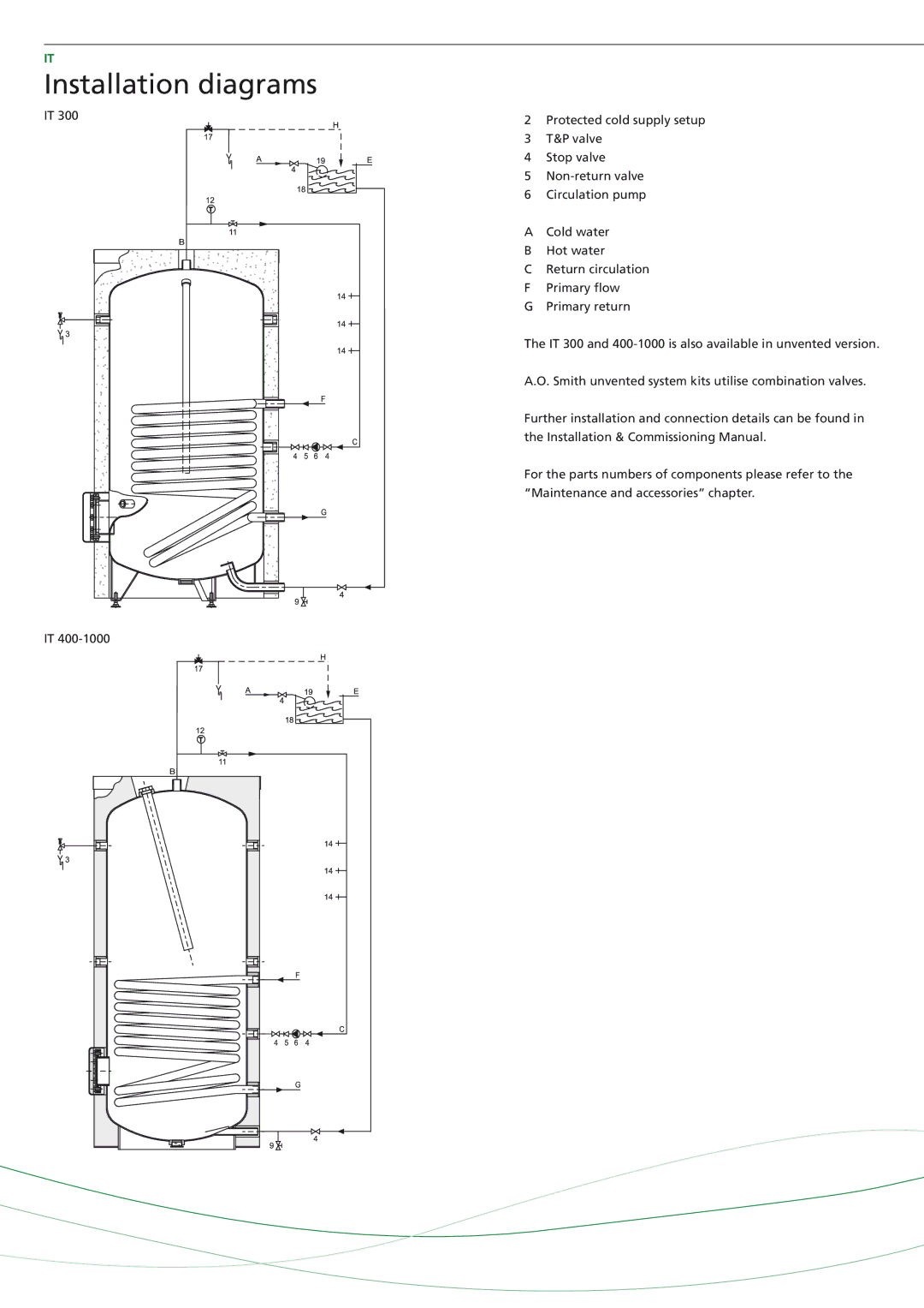
IT - 600, IT - 300, IT - 2500, IT - 500, IT - 2000 specifications
A.O. Smith is a renowned manufacturer of water heating and water treatment solutions, and its IT series presents a remarkable lineup of water heaters designed for industrial and commercial applications. The IT series includes models such as the IT - 1000, IT - 600, IT - 1500, IT - 500, and IT - 400, each specifically engineered to cater to varying demands and capacities.The IT - 1000 is one of the most robust options in the series, offering a significant water heating capacity suitable for large-scale operations. Its innovative design includes a high-efficiency burner that maximizes fuel utilization, resulting in cost savings and reduced emissions. This model often features advanced control systems that allow for precise temperature settings, ensuring that the system operates at optimal efficiency.
In contrast, the IT - 600 is ideal for medium-sized commercial establishments. It combines efficiency with practicality, making it a popular choice for those requiring reliable hot water supply without compromise. The IT - 600 is equipped with state-of-the-art insulation, minimizing heat loss, which aids in maintaining the desired temperature for extended periods.
The IT - 1500 stands out due to its larger tank and higher output capacity, making it suitable for industries with high demand for hot water. It incorporates advanced technology such as smart thermostats and digital controls that allow users to monitor and adjust settings remotely. This model is designed to be durable and efficient, reducing downtime and ensuring that operations run smoothly.
For smaller applications, the IT - 500 and IT - 400 provide excellent solutions. The IT - 500 is compact yet efficient, ideal for businesses with limited space while still maintaining high performance. The IT - 400 is geared towards even lower demand requirements, providing an energy-efficient option for smaller establishments. Both models utilize similar technologies as their larger counterparts, including insulation improvements and user-friendly controls.
Across the entire IT series, A.O. Smith emphasizes energy efficiency, durability, and cutting-edge technology. The integration of smart technology not only enhances user experience but also promotes sustainable operations, aligning with modern industry's push towards greener solutions. In conclusion, A.O. Smith’s IT series offers versatile and reliable water heating options tailored to meet diverse industrial and commercial needs, combining performance and efficiency in every model.

