ITS
Installation diagrams
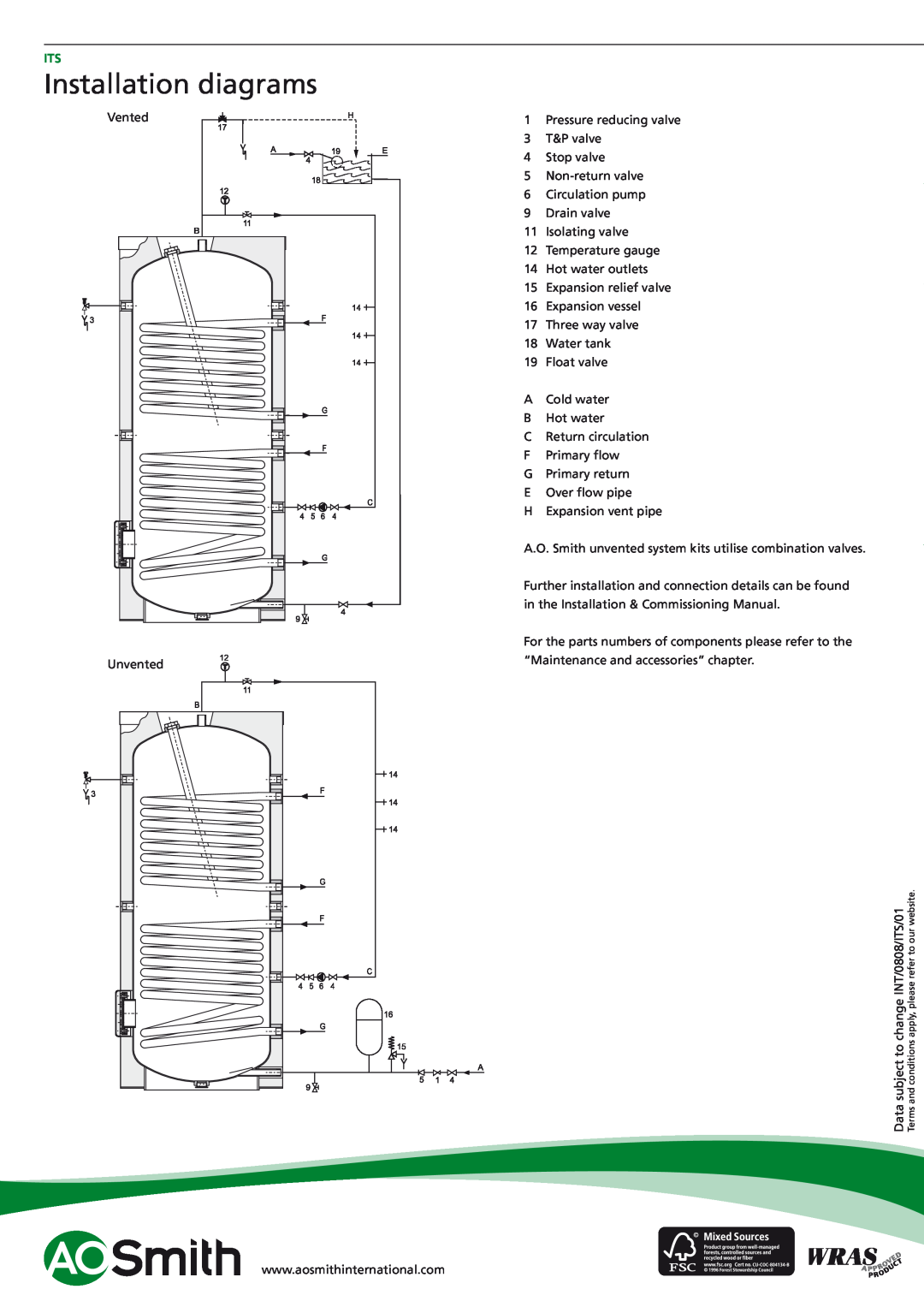
Vented |
Unvented |
1Pressure reducing valve
3T&P valve
4Stop valve
5
6Circulation pump
9Drain valve
11Isolating valve
12Temperature gauge
14Hot water outlets
15Expansion relief valve
16Expansion vessel
17Three way valve
18Water tank
19Float valve
ACold water
BHot water
CReturn circulation
FPrimary flow
GPrimary return
EOver flow pipe
HExpansion vent pipe
A.O. Smith unvented system kits utilise combination valves.
Further installation and connection details can be found in the Installation & Commissioning Manual.
For the parts numbers of components please refer to the “Maintenance and accessories” chapter.
subject to change INT/0808/ITS/01 | and conditions apply, please refer to our website. |
Data | Terms |
www.aosmithinternational.com