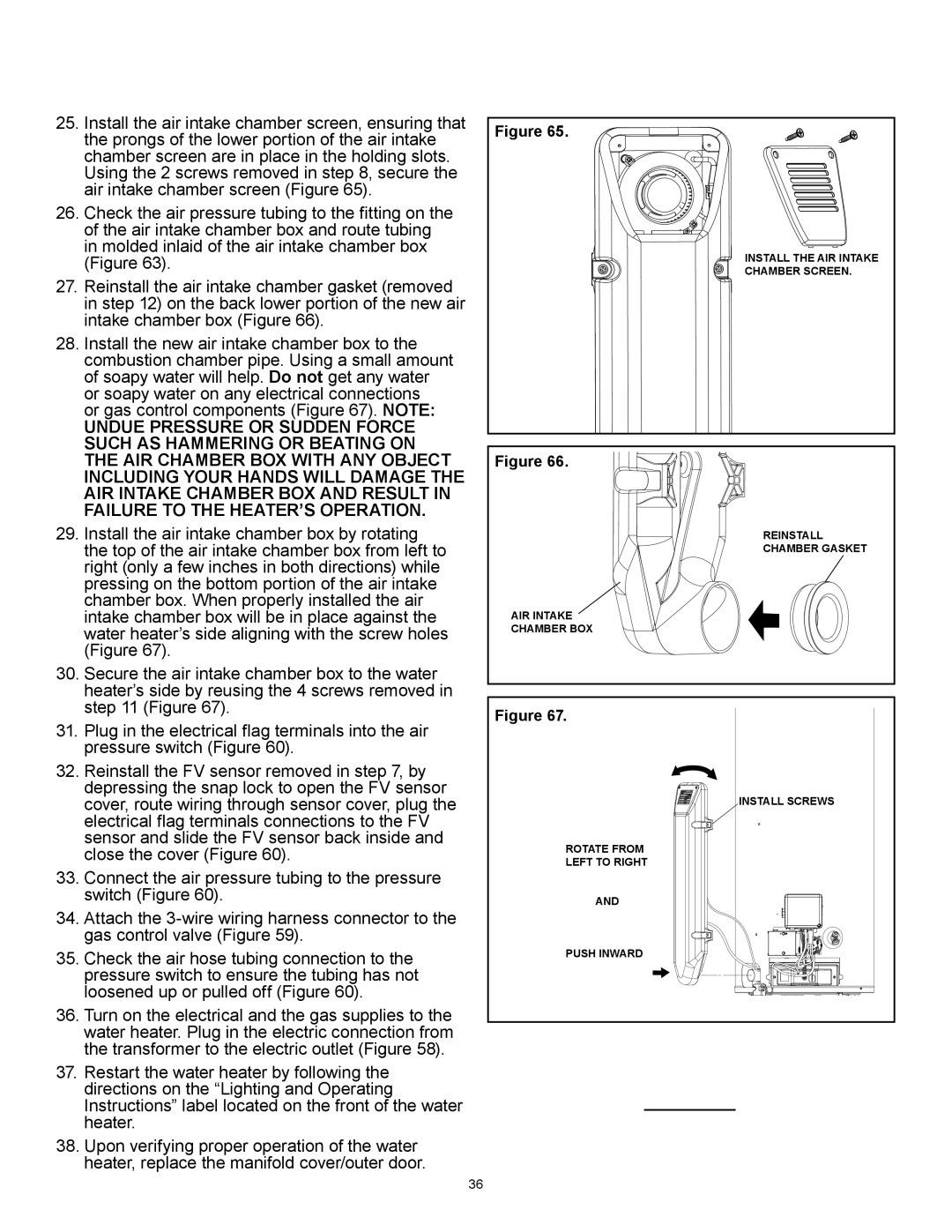
25. | Install the air intake chamber screen, ensuring that |
| the prongs of the lower portion of the air intake |
| chamber screen are in place in the holding slots. |
| Using the 2 screws removed in step 8, secure the |
| air intake chamber screen (Figure 65). |
26. | Check the air pressure tubing to the fitting on the |
| of the air intake chamber box and route tubing |
| in molded inlaid of the air intake chamber box |
| (Figure 63). |
27. | Reinstall the air intake chamber gasket (removed |
| in step 12) on the back lower portion of the new air |
| intake chamber box (Figure 66). |
28. | Install the new air intake chamber box to the |
| combustion chamber pipe. Using a small amount |
| of soapy water will help. Do not get any water |
| or soapy water on any electrical connections |
| or gas control components (Figure 67). NOTE: |
| UNDUE PRESSURE OR SUDDEN FORCE |
| SUCH AS HAMMERING OR BEATING ON |
| THE AIR CHAMBER BOX WITH ANY OBJECT |
| INCLUDING YOUR HANDS WILL DAMAGE THE |
| AIR INTAKE CHAMBER BOX AND RESULT IN |
| FAILURE TO THE HEATER’S OPERATION. |
29. | Install the air intake chamber box by rotating |
| the top of the air intake chamber box from left to |
| right (only a few inches in both directions) while |
| pressing on the bottom portion of the air intake |
| chamber box. When properly installed the air |
| intake chamber box will be in place against the |
| water heater’s side aligning with the screw holes |
| (Figure 67). |
30. | Secure the air intake chamber box to the water |
| heater’s side by reusing the 4 screws removed in |
| step 11 (Figure 67). |
Figure 65.
INSTALL THE AIR INTAKE
CHAMBER SCREEN.
Figure 66.
REINSTALL
CHAMBER GASKET
AIR INTAKE
CHAMBER BOX
31. | Plug in the electrical flag terminals into the air |
| pressure switch (Figure 60). |
32. | Reinstall the FV sensor removed in step 7, by |
| depressing the snap lock to open the FV sensor |
| cover, route wiring through sensor cover, plug the |
| electrical flag terminals connections to the FV |
| sensor and slide the FV sensor back inside and |
| close the cover (Figure 60). |
33. | Connect the air pressure tubing to the pressure |
| switch (Figure 60). |
Figure 67.
ROTATE FROM
LEFT TO RIGHT
INSTALL SCREWS
34. | Attach the |
| gas control valve (Figure 59). |
35. | Check the air hose tubing connection to the |
| pressure switch to ensure the tubing has not |
| loosened up or pulled off (Figure 60). |
36. | Turn on the electrical and the gas supplies to the |
| water heater. Plug in the electric connection from |
| the transformer to the electric outlet (Figure 58). |
37. | Restart the water heater by following the |
| directions on the “Lighting and Operating |
| Instructions” label located on the front of the water |
| heater. |
38. Upon verifying proper operation of the water | |
| heater, replace the manifold cover/outer door. |
AND
PUSH INWARD
36