|
| SECTION 15: TROUBLESHOOTING | |
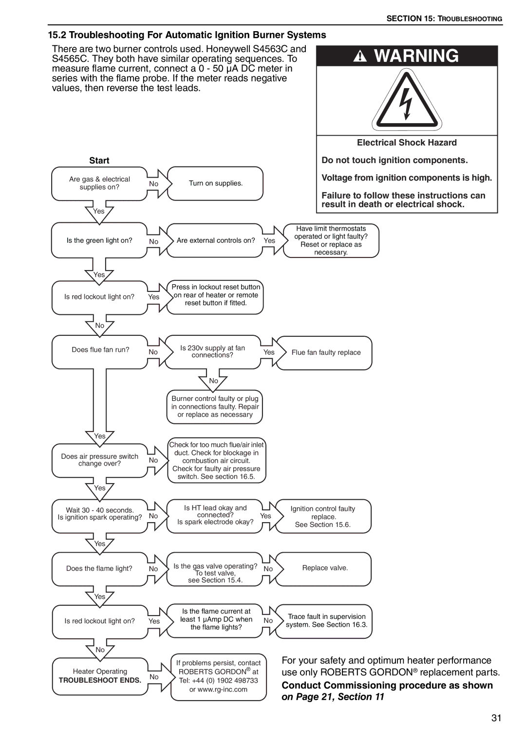
15.2 Troubleshooting For Automatic Ignition Burner Systems | WARNING | ||
S4565C. They both have similar operating sequences. To | |||
There are two burner controls used. Honeywell S4563C and |
|
|
|
measure flame current, connect a 0 - 50 μA DC meter in |
|
|
|
|
|
| |
series with the flame probe. If the meter reads negative |
|
| |
values, then reverse the test leads. |
|
| |
|
|
|
|
| Electrical Shock Hazard | |
Start |
|
|
|
| Do not touch ignition components. | |
Are gas & electrical | No | Turn on supplies. |
|
| Voltage from ignition components is high. | |
supplies on? |
|
|
| |||
|
|
|
| Failure to follow these instructions can | ||
|
|
|
|
| ||
Yes |
|
|
|
| result in death or electrical shock. | |
|
|
|
|
| ||
|
|
| Have limit thermostats | |||
|
|
|
| |||
Is the green light on? | No | Are external controls on? | Yes | operated or light faulty? | ||
Reset or replace as | ||||||
|
|
|
| |||
|
|
|
| necessary. | ||
Yes |
|
|
|
|
| |
|
| Press in lockout reset button |
|
|
| |
Is red lockout light on? | Yes | on rear of heater or remote |
|
|
| |
|
| reset button if fitted. |
|
|
| |
No |
|
|
|
|
| |
Does flue fan run? | No |
|
Yes |
| |
Does air pressure switch | No | |
change over? | ||
|
Yes
Wait 30 - 40 seconds.
Is ignition spark operating? No
Yes |
|
Does the flame light? | No |
Yes |
|
Is red lockout light on? | Yes |
No
Heater Operating
TROUBLESHOOT ENDS. No
Is 230v supply at fan | Yes | |
connections? | ||
|
No
Burner control faulty or plug in connections faulty. Repair or replace as necessary
Check for too much flue/air inlet
duct. Check for blockage in
combustion air circuit.
Check for faulty air pressure
switch. See section 16.5.
Is HT lead okay and
connected? Yes Is spark electrode okay?
Is the gas valve operating? No To test valve,
see Section 15.4.
Is the flame current at
least 1 µAmp DC when No the flame lights?
If problems persist, contact ROBERTS GORDON® at Tel: +44 (0) 1902 498733 or
Flue fan faulty replace
Ignition control faulty replace.
See Section 15.6.
Replace valve.
Trace fault in supervision system. See Section 16.3.
For your safety and optimum heater performance use only ROBERTS GORDON® replacement parts.
Conduct Commissioning procedure as shown on Page 21, Section 11
31