DualAir
Page
2005
Page
Table of Figures
Page
Product Approval
National Standards and Applicable Codes
Clearances to Combustibles
Corrosive Chemicals
Critical Considerations 3.1 Basic Information
Minimum Required Installation Clearances
Electrical Supply
Flue
Installation Clearances and Clearances to Combustibles
Front View Left Version
Specifications 4.1 DAT all models
Model 100 115 Fan Data
General Technical Data Table all models
Model 100 115
2 DAT100 and 115 4 kW motor
Shelf Mounting and Suspension
Heater Installation 5.1 General
Handling
Type B22 Appliance
Flue Installation 6.1 Flue Installation
Air Intake Terminal Cover
Flue Conversion
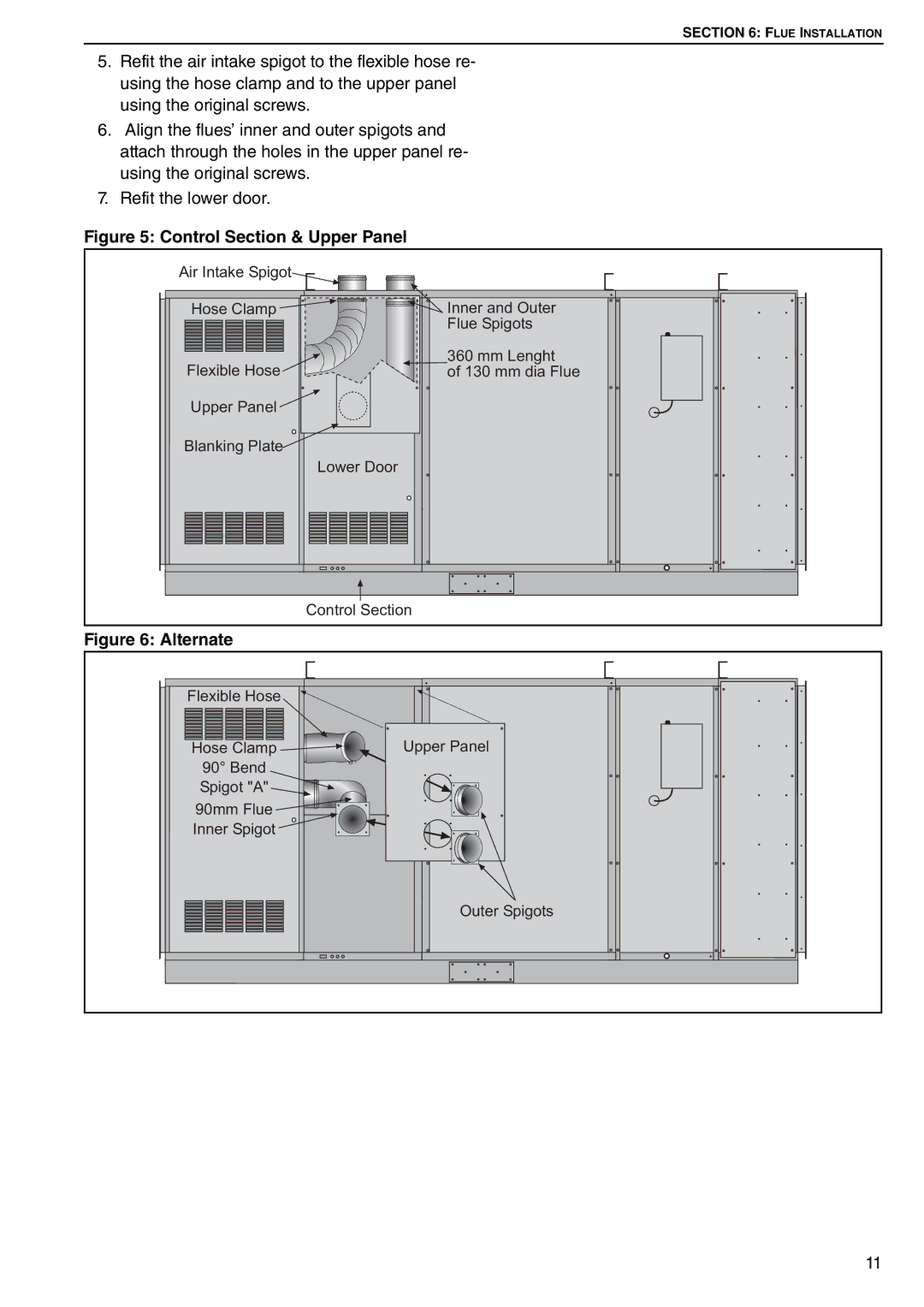
Control Section & Upper Panel
Vertical and Horizontal Flue Termination Type B22 Appliance
Open Flued Installation
Room Sealed Installation
Heaters Installed Within the Heated Space
Building Ventilation
14, .1 and to ensure that there is
Optional Heater Configurations 8.1 Distribution Duct
Department for recommendations regarding
Duct resistance and design. Tel +44 0
Connections
Gas Connection with Stainless Steel Flex Connector
See Page 17, .3 through Page 18, Section
Remote Control
Remote Frost Thermostat
Number
See Page 20, Section
DAT Wiring Diagram Models
Site wiring connections shown
DAT Site Connections at Main Circuit Board
Cooling Coils/Condensers
Gas Fired Heater
Louvers
Electrical Checks
Automatic Burner Control Box Sequence
Commissioning the Gas Valves
Combustion Testing all models
Commissioning the Gas Valve
Set Minimum Pressure
Turning Off the DualAir Unit
Pressure Switch
Complete the Commissioning
Instruction to the User
See Page 25, Section
See Page 26, Section
Heater Operation
See Page 7, .3 and Page 8, Figure
Simple Fault Finding all models
Burner Lockout Reset Button
Simple Fault Finding burner faults
Cooling Section Operation
13.3 Fan/Motor Assembly Maintenance
Burner Maintenance
Heat Exchanger Maintenance
Servicing 13.1 Servicing Instructions
Gas Control Valve Maintenance all models
Gas Valves
Conversion Between Gases 14.1 General
Burner Conversion
Conduct Commissioning procedure as shown on Page 21, Section
Result in death or electrical shock
Troubleshooting For Automatic Ignition Burner Systems
Start
Troubleshooting for Flame Supervision System
Troubleshooting for Main Fan
Troubleshooting for Solenoid Valves
Conduct Commissioning procedure as on Page 21, Section
Troubleshooting for Fan Contactor
Burner Components
Gas Valve Replacement all models
See Page 5, Section
Gas Valve
Burner Injectors
Burner Compartment
Ignition Electrode and Flame Probe
Remove screws securing outlet flange to the flue adapter
See Page 21, Section
Heater Pressure Switch
Filter Pressure Switch
Pressure Switches
Coil Pressure Switch
Fan Motor Removal
Ignition Control
16.7.1 S4563C Models 75 to
Fan Removal and Replacement
Combination Fan/Limit Thermostat
Page
Page
Some objects can catch fire or explode when placed