DUALAIR® HEATING AND COOLING UNITS INSTALLATION OPERATION AND SERVICE MANUAL
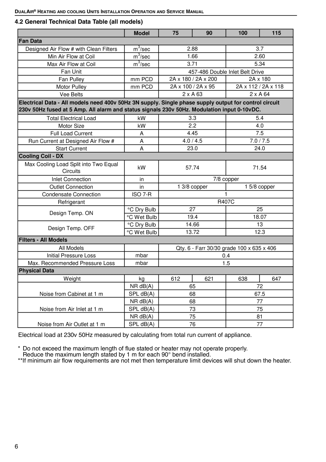
4.2 General Technical Data Table (all models)
| Model | 75 |
| 90 | 100 |
| 115 |
Fan Data |
|
|
|
|
|
|
|
Designed Air Flow # with Clean Filters | m3/sec |
| 2.88 | 3.7 |
| ||
Min Air Flow at Coil | m3/sec |
| 1.66 | 2.60 |
| ||
Max Air Flow at Coil | m3/sec |
| 3.71 | 5.34 |
| ||
Fan Unit |
|
|
| ||||
Fan Pulley | mm PCD | 2A x 180 / 2A x 200 | 2A x 180 |
| |||
Motor Pulley | mm PCD | 2A x 100 / 2A x 95 | 2A x 112 / 2A x 118 | ||||
Vee Belts |
|
| 2 x A 63 | 2 x A 64 |
| ||
Electrical Data - All models need 400v 50Hz 3N supply. Single phase supply output for control circuit 230v 50Hz fused at 5 Amp. All alarm and status signals 230v 50Hz. Modulation input
Total Electrical Load | kW |
| 3.3 |
|
| 5.4 | ||
Motor Size | kW |
| 2.2 |
|
| 4.0 | ||
Full Load Current | A |
| 4.45 |
|
| 7.5 | ||
Run Current at Designed Air Flow # | A |
| 4.0 / 4.5 |
|
| 7.0 / 7.5 | ||
Start Current | A |
| 23.0 |
|
| 24.0 | ||
Cooling Coil - DX |
|
|
|
|
|
|
|
|
Max Cooling Load Split into Two Equal | kW |
| 57.74 |
|
| 71.54 | ||
Circuits |
|
|
| |||||
|
|
|
|
|
|
|
| |
Inlet Connection | in |
| 7/8 | copper |
|
| ||
Outlet Connection | in | 1 3/8 copper |
| 1 5/8 copper | ||||
Condensate Connection | ISO |
|
|
| 1 |
|
| |
Refrigerant |
|
|
|
| R407C |
|
| |
Design Temp. ON | °C Dry Bulb |
| 27 |
|
| 25 | ||
°C Wet Bulb |
| 19.4 |
|
| 18.07 | |||
|
|
|
| |||||
Design Temp. OFF | °C Dry Bulb |
| 14.66 |
|
| 13 | ||
°C Wet Bulb |
| 13.72 |
|
| 12.3 | |||
|
|
|
| |||||
Filters - All Models |
|
|
|
|
|
|
|
|
All Models |
| Qty. 6 - Farr 30/30 grade 100 x 635 x 406 | ||||||
Initial Pressure Loss | mbar |
|
|
| 0.4 |
|
| |
Max. Recommended Pressure Loss | mbar |
|
|
| 1.5 |
|
| |
Physical Data |
|
|
|
|
|
|
|
|
Weight | kg | 612 |
| 621 |
| 638 |
| 647 |
| NR dB(A) |
| 65 |
|
| 72 | ||
Noise from Cabinet at 1 m | SPL dB(A) |
| 68 |
|
| 67.5 | ||
| NR dB(A) |
| 68 |
|
| 77 | ||
Noise from Air Inlet at 1 m | SPL dB(A) |
| 73 |
|
| 75 | ||
| NR dB(A) |
| 75 |
|
| 81 | ||
Noise from Air Outlet at 1 m | SPL dB(A) |
| 76 |
|
| 77 | ||
Electrical load at 230v 50Hz measured by calculating from total run current of appliance.
* Do not exceed the maximum length of flue stated or heater may not operate properly. Reduce the maximum length stated by 1 m for each 90° bend installed.
**If minimum air flow requirements are not met then temperature limit devices will shut down the heater.
6
