DUALAIR® HEATING AND COOLING UNITS INSTALLATION OPERATION AND SERVICE MANUAL
SECTION 6: FLUE INSTALLATION 6.1 Flue Installation
![]() WARNING
WARNING
Fire Hazard
Some objects will catch fire or explode when placed close to the heater section.
Keep all flammable objects, liquids and vapours the required distance away from the heater section.
Failure to follow these instructions can result in death, injury or property damage.
The flue must terminate outside of the building. Flues and air intakes must be fully sealed and correctly sized for the model. Flues should be assembled as detailed on Page 10, Figure 4 through Page 12, Figure 8. The joints between the flue terminal and the roof or wall must be sealed. If the flue passes through a wall or ceiling of combustible material it must be enclosed by a sleeve of non- combustible material and be separated from the sleeve by at least a 25 mm air gap.
Flues and air intakes must be adequately supported so that the DualAir® unit does not bear the weight of the pipes.
For flue termination See Page 10, Figure 4 through Page 12, Figure 8.
6.2Type C12, C32 & C62 Appliance Room Sealed.
The heaters are designed to be installed as room sealed appliances. The flue and air intake are run as separate pipes to the concentric wall or roof
terminal. See Page 12, Figure 8.
6.3 Type B22 Appliance
The flue must terminate outside the building and be fitted with a low resistance terminal.
See Page 10, Figure 4 through Page 12, Figure 7.
6.3.1 Air Intake Terminal Cover
For Type B22 appliance installations, an Air Intake Terminal Cover is an available option. The cover is scored flat sheet metal that must be bent into shape. See Page 12, Figure 7. Remove and retain the screws for the Air Inlet spigot. Use these screws to attach the cover in position over the spigot.
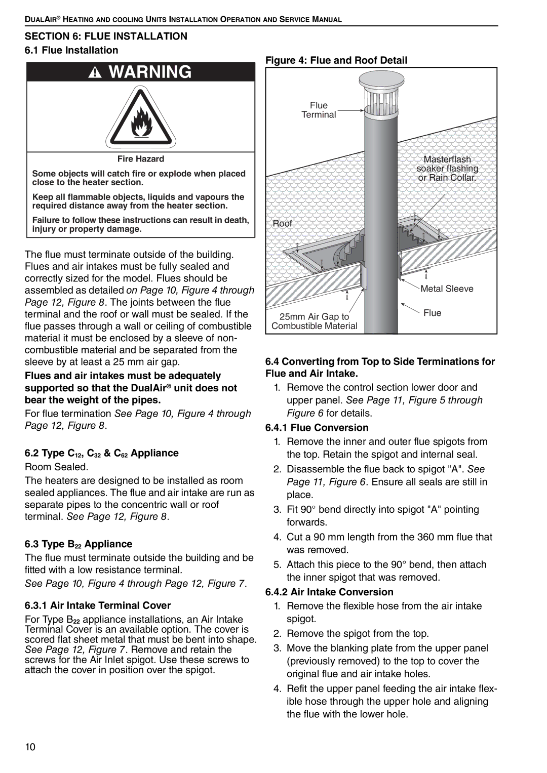
Figure 4: Flue and Roof Detail
Flue |
|
Terminal |
|
| Masterflash |
| soaker flashing |
| or Rain Collar. |
Roof |
|
| Metal Sleeve |
25mm Air Gap to | Flue |
| |
Combustible Material |
|
6.4Converting from Top to Side Terminations for Flue and Air Intake.
1.Remove the control section lower door and upper panel. See Page 11, Figure 5 through Figure 6 for details.
6.4.1 Flue Conversion
1.Remove the inner and outer flue spigots from the top. Retain the spigot and internal seal.
2.Disassemble the flue back to spigot "A". See Page 11, Figure 6. Ensure all seals are still in place.
3.Fit 90° bend directly into spigot "A" pointing forwards.
4.Cut a 90 mm length from the 360 mm flue that was removed.
5.Attach this piece to the 90° bend, then attach the inner spigot that was removed.
6.4.2Air Intake Conversion
1.Remove the flexible hose from the air intake spigot.
2.Remove the spigot from the top.
3.Move the blanking plate from the upper panel (previously removed) to the top to cover the original flue and air intake holes.
4.Refit the upper panel feeding the air intake flex- ible hose through the upper hole and aligning the flue with the lower hole.
10