SECTION 12: USER INSTRUCTIONS
SECTION 12: USER INSTRUCTIONS 12.1 User Instructions
The DualAir® units are fully automatic and operate from the external controls fitted on site.
The only user controls at the heater are the:
Burner lockout |
|
reset button | See Page 26, Section 12.3.3 |
Limit thermostat |
|
reset | See Page 25, Section 12.3.1 |
Second limit thermostat | |
reset button | See Page 25, Section 12.3.2 |
![]() WARNING
WARNING
Electrical Shock Hazard Disconnect electrical power before servicing.
Failure to follow these instructions can result in death or electrical shock.
12.2 Heater Operation
When the heater has been switched on by the remote controls installed, the main burner will automatically turn on.
The burner control box will control the ignition of the flame.
All heaters require a constant gas and electricity supply which must not be interrupted during the normal operation of this heater.
12.2.1 Warning Lights
The DualAir® unit has three warning lights; GREEN = Heater ON, burner attempting to fire RED = Burner LOCKOUT, see Section 12.3.3. AMBER = Dirty Filter, replace filter, air flow is dropping to an unacceptably low value.
Figure 14: Heater Operating Sequence
| ON | CLOSE |
THERMOSTAT |
| DOWN |
CALL FOR |
|
|
HEAT | ON |
|
BURNER |
|
|
RUN ON |
| |
|
| RUN ON |
FAN |
|
|
12.3Common User Controls (all models) 12.3.1 Combination Fan/Limit Thermostat
The Combination Fan/Limit Thermostat is located inside the access door at the top of the heater. See Page 37, Section 16.3.
This control ensures the heater does not blow cold air in the normal heating cycle and protects the heat exchanger against overheating.
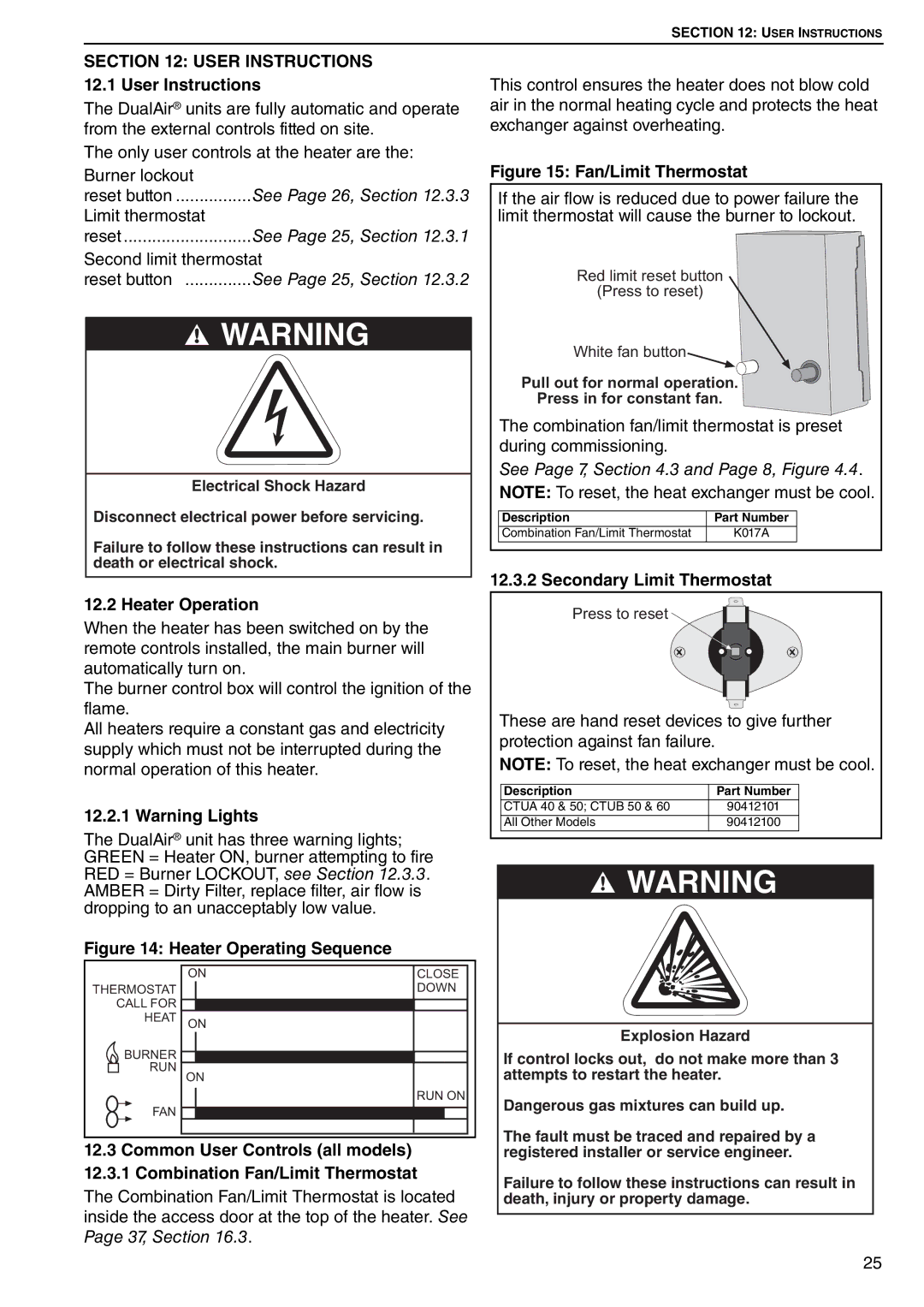
Figure 15: Fan/Limit Thermostat
If the air flow is reduced due to power failure the limit thermostat will cause the burner to lockout.
Red limit reset button
(Press to reset)
White fan button
Pull out for normal operation.
Press in for constant fan.
The combination fan/limit thermostat is preset during commissioning.
See Page 7, Section 4.3 and Page 8, Figure 4.4.
NOTE: To reset, the heat exchanger must be cool.
Description | Part Number |
Combination Fan/Limit Thermostat | K017A |
12.3.2Secondary Limit Thermostat
Press to reset
These are hand reset devices to give further protection against fan failure.
NOTE: To reset, the heat exchanger must be cool.
Description | Part Number |
CTUA 40 & 50; CTUB 50 & 60 | 90412101 |
All Other Models | 90412100 |
![]() WARNING
WARNING
Explosion Hazard
If control locks out, do not make more than 3 attempts to restart the heater.
Dangerous gas mixtures can build up.
The fault must be traced and repaired by a registered installer or service engineer.
Failure to follow these instructions can result in death, injury or property damage.
25