Combination of Gain Mode
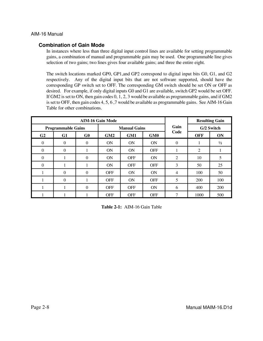
In instances where less than three digital input control lines are available for setting programmable gains, a combination of manual and programmable gain may be used. One programmable line gives selection of two gains; two lines gives four available gains; and three the entire eight.
The switch locations marked GP0, GP1,and GP2 correspond to digital input bits G0, G1, and G2 respectively. Any of the digital input bits that are not software supported, should have the corresponding GP switch set to OFF. The corresponding GM switch should be set ON or OFF as desired. For example, if only digital inputs G0 and G1 are available, switch GP2 would be set OFF. If GM2 is set to ON, then gain codes 0, 1, 2, 3 would be available as programmable gains, and if GM2 is set to OFF, then gain codes 4, 5, 6 ,7 would be available as programmable gains. See
|
|
|
|
|
|
| Resulting Gain | |||
|
|
|
|
|
|
|
| Gain |
|
|
Programmable Gains |
| Manual Gains |
| G/2 Switch | ||||||
|
| Code | ||||||||
|
|
|
|
|
|
|
|
|
| |
G2 | G1 | G0 | GM2 |
| GM1 |
| GM0 | OFF | ON | |
|
|
| ||||||||
0 | 0 | 0 | ON |
| ON |
| ON | 0 | 1 | ½ |
|
|
|
|
|
|
|
|
|
|
|
0 | 0 | 1 | ON |
| ON |
| OFF | 1 | 2 | 1 |
|
|
|
|
|
|
|
|
|
|
|
0 | 1 | 0 | ON |
| OFF |
| ON | 2 | 10 | 5 |
|
|
|
|
|
|
|
|
|
|
|
0 | 1 | 1 | ON |
| OFF |
| OFF | 3 | 50 | 25 |
|
|
|
|
|
|
|
|
|
|
|
1 | 0 | 0 | OFF |
| ON |
| ON | 4 | 100 | 50 |
|
|
|
|
|
|
|
|
|
|
|
1 | 0 | 1 | OFF |
| ON |
| OFF | 5 | 200 | 100 |
|
|
|
|
|
|
|
|
|
|
|
1 | 1 | 0 | OFF |
| OFF |
| ON | 6 | 400 | 200 |
|
|
|
|
|
|
|
|
|
|
|
1 | 1 | 1 | OFF |
| OFF |
| OFF | 7 | 1000 | 500 |
Table
Page | Manual |
