CheetaHub Classic-2041
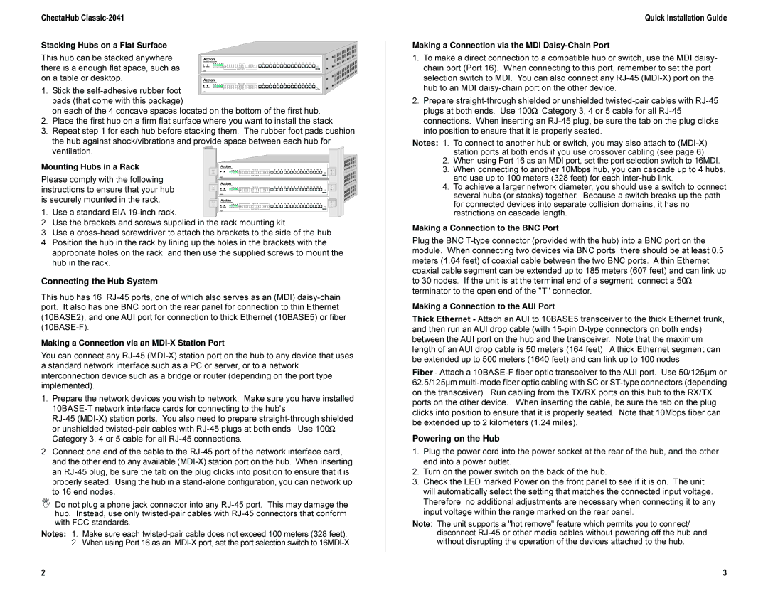
Stacking Hubs on a Flat Surface
This hub can be stacked anywhere there is a enough flat space, such as on a table or desktop.
1. Stick the self-adhesive rubber foot pads (that come with this package)
on each of the 4 concave spaces located on the bottom of the first hub.
2.Place the first hub on a firm flat surface where you want to install the stack.
3.Repeat step 1 for each hub before stacking them. The rubber foot pads cushion the hub against shock/vibrations and provide space between each hub for
ventilation.
Mounting Hubs in a Rack
Please comply with the following instructions to ensure that your hub is securely mounted in the rack.
1. Use a standard EIA 19-inch rack.
2.Use the brackets and screws supplied in the rack mounting kit.
3.Use a cross-head screwdriver to attach the brackets to the side of the hub.
4.Position the hub in the rack by lining up the holes in the brackets with the appropriate holes on the rack, and then use the supplied screws to mount the hub in the rack.
Connecting the Hub System
This hub has 16 RJ-45 ports, one of which also serves as an (MDI) daisy-chain port. It also has one BNC port on the rear panel for connection to thin Ethernet (10BASE2), and one AUI port for connection to thick Ethernet (10BASE5) or fiber (10BASE-F).
Making a Connection via an MDI-X Station Port
You can connect any RJ-45 (MDI-X) station port on the hub to any device that uses a standard network interface such as a PC or server, or to a network interconnection device such as a bridge or router (depending on the port type implemented).
1.Prepare the network devices you wish to network. Make sure you have installed 10BASE-T network interface cards for connecting to the hub's
RJ-45 (MDI-X) station ports. You also need to prepare straight-through shielded or unshielded twisted-pair cables with RJ-45 plugs at both ends. Use 100W Category 3, 4 or 5 cable for all RJ-45 connections.
2.Connect one end of the cable to the RJ-45 port of the network interface card, and the other end to any available (MDI-X) station port on the hub. When inserting an RJ-45 plug, be sure the tab on the plug clicks into position to ensure that it is properly seated. Using the hub in a stand-alone configuration, you can network up to 16 end nodes.
ΙDo not plug a phone jack connector into any RJ-45 port. This may damage the hub. Instead, use only twisted-pair cables with RJ-45 connectors that conform with FCC standards.
Notes: 1. Make sure each twisted-pair cable does not exceed 100 meters (328 feet). 2. When using Port 16 as an MDI-X port, set the port selection switch to 16MDI-X.
Quick Installation Guide
Making a Connection via the MDI Daisy-Chain Port
1.To make a direct connection to a compatible hub or switch, use the MDI daisy- chain port (Port 16). When connecting to this port, remember to set the port selection switch to MDI. You can also connect any RJ-45 (MDI-X) port on the hub to an MDI daisy-chain port on the other device.
2.Prepare straight-through shielded or unshielded twisted-pair cables with RJ-45 plugs at both ends. Use 100W Category 3, 4 or 5 cable for all RJ-45 connections. When inserting an RJ-45 plug, be sure the tab on the plug clicks into position to ensure that it is properly seated.
Notes: 1. To connect to another hub or switch, you may also attach to (MDI-X) station ports at both ends if you use crossover cabling (see page 6).
2.When using Port 16 as an MDI port, set the port selection switch to 16MDI.
3.When connecting to another 10Mbps hub, you can cascade up to 4 hubs, and use up to 100 meters (328 feet) for each inter-hub link.
4.To achieve a larger network diameter, you should use a switch to connect several hubs (or stacks) together. Because a switch breaks up the path for connected devices into separate collision domains, it has no restrictions on cascade length.
Making a Connection to the BNC Port
Plug the BNC T-type connector (provided with the hub) into a BNC port on the module. When connecting two devices via BNC ports, there should be at least 0.5 meters (1.64 feet) of coaxial cable between the two BNC ports. A thin Ethernet coaxial cable segment can be extended up to 185 meters (607 feet) and can link up to 30 nodes. If the unit is at the terminal end of a segment, connect a 50W terminator to the open end of the "T" connector.
Making a Connection to the AUI Port
Thick Ethernet - Attach an AUI to 10BASE5 transceiver to the thick Ethernet trunk, and then run an AUI drop cable (with 15-pin D-type connectors on both ends) between the AUI port on the hub and the transceiver. Note that the maximum length of an AUI drop cable is 50 meters (164 feet). A thick Ethernet segment can be extended up to 500 meters (1640 feet) and can link up to 100 nodes.
Fiber - Attach a 10BASE-F fiber optic transceiver to the AUI port. Use 50/125µm or 62.5/125µm multi-mode fiber optic cabling with SC or ST-type connectors (depending on the transceiver). Run cabling from the TX/RX ports on this hub to the RX/TX ports on the other device. When inserting the cable, be sure the tab on the plug clicks into position to ensure that it is properly seated. Note that 10Mbps fiber can be extended up to 2 kilometers (1.24 miles).
Powering on the Hub
1.Plug the power cord into the power socket at the rear of the hub, and the other end into a power outlet.
2.Turn on the power switch on the back of the hub.
3.Check the LED marked Power on the front panel to see if it is on. The unit will automatically select the setting that matches the connected input voltage. Therefore, no additional adjustments are necessary when connecting it to any input voltage within the range marked on the rear panel.
Note: The unit supports a "hot remove" feature which permits you to connect/ disconnect RJ-45 or other media cables without powering off the hub and without disrupting the operation of the devices attached to the hub.