General Information
Before You Begin
Before proceeding with the disassembly procedure, make sure that you do the following:
1.Turn off the power to the system and all peripherals.
2.Unplug the AC adapter and all power and signal cables from the system.
3.Remove the battery pack.
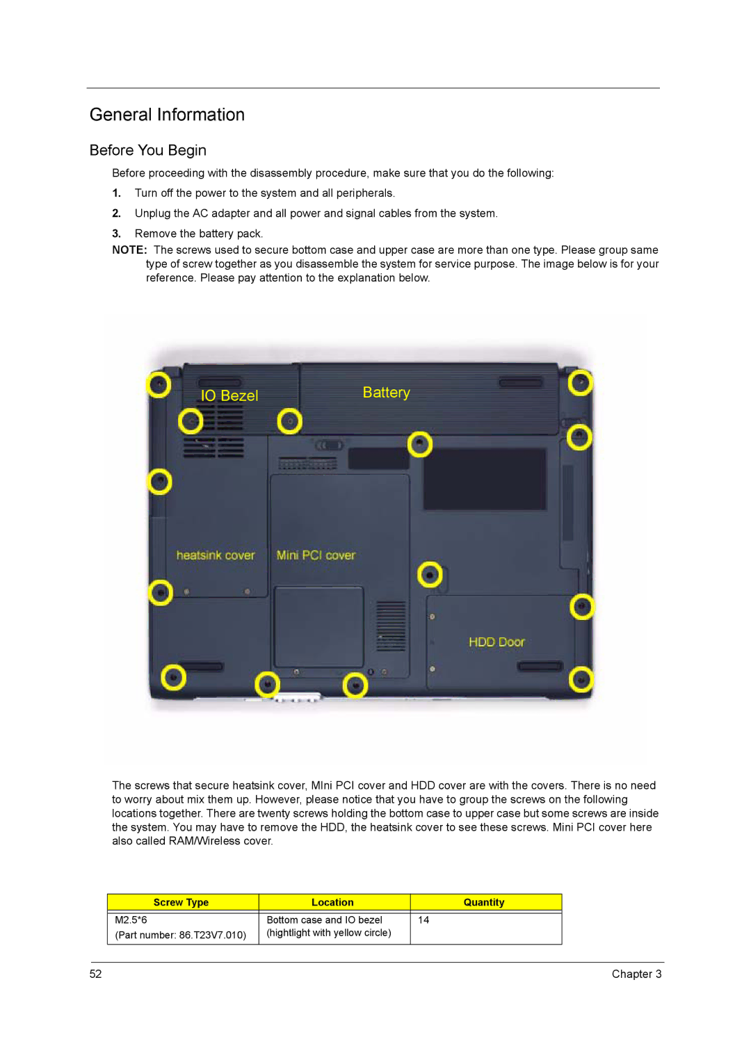
NOTE: The screws used to secure bottom case and upper case are more than one type. Please group same type of screw together as you disassemble the system for service purpose. The image below is for your reference. Please pay attention to the explanation below.
IO Bezel | Battery |
The screws that secure heatsink cover, MIni PCI cover and HDD cover are with the covers. There is no need to worry about mix them up. However, please notice that you have to group the screws on the following locations together. There are twenty screws holding the bottom case to upper case but some screws are inside the system. You may have to remove the HDD, the heatsink cover to see these screws. Mini PCI cover here also called RAM/Wireless cover.
Screw Type | Location | Quantity |
|
|
|
M2.5*6 | Bottom case and IO bezel | 14 |
(Part number: 86.T23V7.010) | (hightlight with yellow circle) |
|
|
|
|
52 | Chapter 3 |